data link layer
play

Data Link Layer Understand principles behind data link layer - PDF document

Chapter 5: The Data Link Layer Goals: Data Link Layer Understand principles behind data link layer services: Error detection, correction CS 3516 Computer Networks CS 3516 Computer Networks Sharing a broadcast channel: multiple


  1. Chapter 5: The Data Link Layer Goals: Data Link Layer • Understand principles behind data link layer services: – Error detection, correction CS 3516 – Computer Networks CS 3516 Computer Networks – Sharing a broadcast channel: multiple access Sharing a broadcast channel: multiple access – Link layer addressing – Reliable data transfer, flow control ( done! in Ch3 ) • Instantiation and implementation of various link layer technologies 
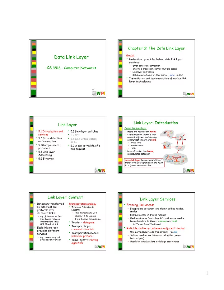
Link Layer: Introduction Link Layer Some terminology: • 5.1 Introduction and • 5.6 Link-layer switches • Hosts and routers are nodes • 5.7 PPP • Communication channels that services • 5.2 Error detection • 5.8 Link virtualization: connect adjacent nodes along communication path are links and correction MPLS – Wired links • 5 3Multiple access • 5 9 A d • 5.9 A day in the life of a 5.3Multiple access i th lif f – Wireless links Wi l li k protocols web request – LANs • 5.4 Link-layer • Layer-2 packet is a frame, encapsulates datagram Addressing • 5.5 Ethernet data-link layer has responsibility of transferring datagram from one node to adjacent node over link Link Layer: Context Link Layer Services • Datagram transferred • Framing, link access Transportation analogy • Trip from Princeton to by different link – Encapsulate datagram into frame , adding header, protocols over Lausanne trailer different links: – limo: Princeton to JFK – Channel access if shared medium – plane: JFK to Geneva – e.g., Ethernet on first – Medium Access Control (MAC) addresses used in link, frame relay on – train: Geneva to Lausanne • Tourist = datagram frame headers to identify source and dest frame headers to identify source and dest intermediate links, intermediate links d • Different from IP address! 802.11 on last link • Transport hop = • Each link protocol • Reliable delivery between adjacent nodes communication link provides different • Transportation mode = – We learned how to do this already! (in ch3) services – Seldom used on low bit-error link (fiber, some link layer protocol – e.g., may or may not • Travel agent = routing twisted pair) provide rdt over link – Used for wireless li nks with high error rates algorithm 1

  2. Link Layer Services (more) Where is Link Layer Implemented? • Flow control • In each and every host • Link layer implemented in – Pacing between adjacent sending and receiving nodes • Error detection “adaptor” (aka network host schematic – Errors caused by signal attenuation, noise. interface card NIC) application transport – Receiver detects presence of errors – Ethernet card, PCMCI card, network cpu memory • Signals sender for retransmission or drops frame 802.11 card link link • Error correction – Implements link, physical host layer bus controller • Attaches into host’s (e.g., PCI) – Receiver identifies and corrects bit error(s) without link physical resorting to retransmission physical system buses • Half-duplex and full-duplex transmission • Combination of hardware, network adapter – With half duplex, nodes at both ends of link can software, and firmware card transmit, but not at same time Adaptors Communicating Data Link Layer • 5.1 Introduction and • 5.6 Link-layer switches • 5.7 PPP services datagram datagram • 5.2 Error detection • 5.8 Link virtualization: controller controller and correction MPLS • 5 3 Multiple access • 5.9 A day in the life of a • 5 9 A d sending host receiving host 5.3 Multiple access i th lif f datagram protocols web request frame • 5.4 Link-layer • Sending side: • Receiving side Addressing • 5.5 Ethernet – Encapsulates datagram in – Looks for errors, rdt, flow frame control, etc. – Adds error checking bits, – Extracts datagram, passes rdt, flow control, etc. to upper layer Simple - Parity Checking Error Detection EDC = Error Detection and Correction bits (redundancy) Single Bit Parity: Two Dimensional Bit Parity : D = Data protected by error checking, may include header fields Detect single bit errors Detect and correct single bit errors • Error detection not 100% reliable! ― Protocol may miss some errors, but rarely ― Larger EDC field yields better detection and correction otherwise 0 0 2

  3. Checksumming: Cyclic Redundancy Check (CRC) Internet Checksum (review) • View data bits, D, as a binary number Goal: detect “errors” (e.g. flipped bits) in transmitted • Choose r +1 bit pattern (generator), G packet • Goal: choose r CRC bits, R, such that – <D,R> exactly divisible by G (modulo 2) Sender: Receiver: – Receiver knows G , divides <D,R> by G . • Treat segment contents • Compute checksum of • If non-zero remainder � error detected! as sequence of 16-bit s s f 16 bit received segment i d s t – Can detect all burst errors less than r+1 bits • Check if computed checksum integers • Widely used in practice (Ethernet, 802.11 WiFi) • Checksum: addition (1’s equals checksum field value: complement sum) of – NO - error detected segment contents – YES - no error detected. • Sender puts checksum But maybe errors value into UDP checksum nonetheless? field CRC Example – Choosing R CRC Standards Want: D . 2 r XOR R = nG • Defined for 8, 12, 16 and 32 bit genrators (G) • CRC-32 adopted by many IEEE link-layer Equivalently: D . 2 r = nG XOR R protocols uses generator: Equivalently: Equivalently – G crc-32 = 100000100110000010001110110110111 G 100000100110000010001110110110111 If we divide D . 2 r by • Detects all errors burst less than 33 bits G, want remainder R • Detects all odd number bit errors • Burst errors greater than 33 bits with probability 1-0.5 r D . 2 r R = remainder[ ] G Multiple Access Links and Protocols Data Link Layer Two types of “links”: • point-to-point (not shared) • 5.1 Introduction and • 5.6 Link-layer switches • 5.7 PPP services – PPP for dial-up access • 5.2 Error detection • 5.8 Link virtualization: – point-to-point link between Ethernet switch and host • broadcast (shared wire or medium) and correction MPLS • 5 3 Multiple access • 5 9 A d • 5.9 A day in the life of a – old-fashioned Ethernet old fashioned Ethernet 5.3 Multiple access i th lif f – upstream HFC protocols web request • 5.4 Link-layer – 802.11 wireless LAN Addressing • 5.5 Ethernet humans at a shared wire (e.g., shared RF cocktail party shared RF cabled Ethernet) (e.g., 802.11 WiFi) (shared air, acoustical) (satellite) 3

  4. Multiple Access Protocols Ideal Multiple Access Protocol • Single shared broadcast channel • Two or more simultaneous transmissions by nodes Broadcast channel of rate R bps � interference 1. When one node wants to transmit, it can send at – collision if node receives two or more signals at the same time rate R Multiple access protocol 2. When M nodes want to transmit, each can send at , • Distributed algorithm determines how nodes share average rate R/M (no overhead) channel (i.e. determine when/who node can transmit) 3. Fully decentralized • Communication about channel sharing must use channel – No special node to coordinate transmissions itself! – No synchronization of clocks, slots – no “out-of-band” channel for coordination 4. Simple MAC Protocols: a Taxonomy Channel Partitioning MAC protocols: TDMA Three broad classes: TDMA: time division multiple access • Channel Partitioning • Access to channel in "rounds" – Divide channel into smaller “pieces” (time slots, • Each station gets fixed length slot (length = pkt frequency) trans time) in each round – Allocate piece to node for exclusive use • Unused slots go idle • Random Access • Random Access Unused slots go idle • Example: 6-station LAN, 1,3,4 have pkt, slots 2,5,6 – Channel not divided, allow collisions idle – “Recover” from collisions • Taking turns 6-slot – Nodes take turns, but nodes with more to send can frame perhaps take longer turns 1 3 4 1 3 4 Random Access Protocols Channel Partitioning MAC protocols: FDMA • When node has packet to send FDMA: frequency division multiple access • Channel spectrum divided into frequency bands – Transmit at full channel data rate R – No a priori coordination among nodes • Each station assigned fixed frequency band • Two or more transmitting nodes ➜ “collision” • Unused transmission time in frequency bands go idle • Random access MAC protocol specifies: • Example: 6-station LAN 1 3 4 have pkt frequency Example: 6-station LAN, 1,3,4 have pkt, frequency – How to detect collisions H d ll bands 2,5,6 idle – How to recover from collisions (e.g. via delayed frequency bands retransmissions) • Examples of random access MAC protocols – slotted ALOHA – ALOHA – CSMA, CSMA/CD, CSMA/CA FDM cable 4

Download Presentation
Download Policy: The content available on the website is offered to you 'AS IS' for your personal information and use only. It cannot be commercialized, licensed, or distributed on other websites without prior consent from the author. To download a presentation, simply click this link. If you encounter any difficulties during the download process, it's possible that the publisher has removed the file from their server.

Recommend


More recommend