
SLIDE 1
3
Data Link Layer
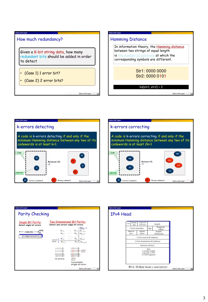
How much redundancy?
Data Link Layer
13
Given a K-bit string data, how many redundant bits should be added in order to detect
- (Case 1) 1 error bit?
- (Case 2) 2 error bits?
Data Link Layer
Hamming Distance
Data Link Layer
14
In information theory, the Hamming distance between two strings of equal length is the number of positions at which the corresponding symbols are different.
Str1: 0000 0000 Str2: 0000 0101
hd(str1, str2) = 2
Data Link Layer
k-errors detecting
Data Link Layer
15
A code is k-errors detecting if and only if the minimum Hamming distance between any two of its codewords is at least k+1.
00 01 10 11 00 Correct codeword Wrong codeword 10 00 11
Minimum HD =2
codeword Code
Data Link Layer
codeword Code
k-errors correcting
Data Link Layer
16
A code is k-errors correcting if and only if the minimum Hamming distance between any two of its codewords is at least 2k+1
00 Correct codeword Wrong codeword 10 000 111 000
001 101
111
Minimum HD =3 Data Link Layer
Parity Checking
Single Bit Parity:
Detect single bit errors
Two Dimensional Bit Parity:
Detect and correct single bit errors
Data Link Layer
17
Data Link Layer
IPv4 Head
IPv4: 20-Byte head + size(option)
Data Link Layer
18