Lecture 16 Logistics HW6 due Wednesday Midterm 2 creeping up (next - - PDF document

lecture 16
SMART_READER_LITE
LIVE PREVIEW

Lecture 16 Logistics HW6 due Wednesday Midterm 2 creeping up (next - - PDF document

Lecture 16 Logistics HW6 due Wednesday Midterm 2 creeping up (next week Wednesday 5/21) Midterm 2 creeping up (next week Wednesday 5/21) Midterm 2 covers materials up to Friday lecture & HW7 Review next Tuesday 6:30pm?


slide-1
SLIDE 1

Lecture 16

Logistics

HW6 due Wednesday Midterm 2 creeping up (next week Wednesday 5/21) Midterm 2 creeping up (next week Wednesday 5/21) Midterm 2 covers materials up to Friday lecture & HW7 Review next Tuesday 6:30pm?

Last lecture

Timing issues for asynchronous inputs Registers/counters Wrapped up on sequential logic building blocks

1

CSE370, Lecture 18

Today

Introduction to finite state machines Counters as finite state machines 16

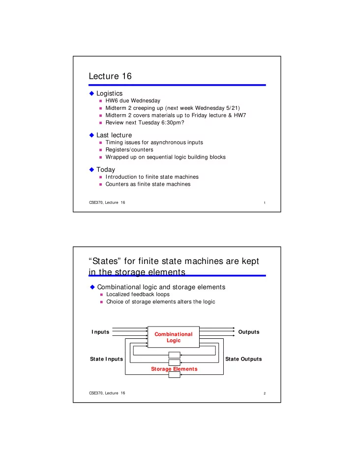
“States” for finite state machines are kept in the storage elements

Combinational logic and storage elements

Localized feedback loops

Combinational Logic Outputs I nputs

Choice of storage elements alters the logic

2

CSE370, Lecture 18

Storage Elements State Outputs State I nputs

16

slide-2
SLIDE 2

Finite-state machines (FSMs)

States: Possible storage-element values Transitions: Changes in state

010 111 001

Transitions: Changes in state

Clock synchronizes the state changes

Sequential logic

Sequences through a series of states Based on inputs and present state

4

CSE370, Lecture 18

In = 0 In = 1 In = 0 In = 1 100 010 110 111 001

16

OUT1 OUT2 OUT3

Drawing state diagrams

Show input values

  • n transition arcs

100 110 1 1 1 1 1 D Q D Q D Q IN CLK

Show output values

in state nodes

5

CSE370, Lecture 18

111 011 101 010 000 001 1 1 1

16

slide-3
SLIDE 3

Counters revisited

Great simple examples of state machines

Output is the counter’s state

010 011 001

Next state is well defined

Does not depend on input (no inputs)

6

CSE370, Lecture 18

100 110 000 101 111 3-bit up-counter

16

FSM design procedure (using counters)

  • 1. Draw a state diagram
  • 2. Draw a state-transition table
  • 2. Draw a state transition table
  • 3. Encode the next-state functions

Minimize the logic using k-maps

4.

Implement the design ll ‘ b ’ l

7

CSE370, Lecture 18

We will use a ‘3-bit up counter’ as an example in two different ways today

16

slide-4
SLIDE 4
  • 1. Draw a state diagram

010 100 011 001 000 3-bit up-counter

8

CSE370, Lecture 18

110 101 111

16

  • 2. Draw a state-transition table

Like a truth-table

State encoding is easy for counters → Use count value

current state next state 000 001 1 1 001 010 2 2 010 011 3 3 011 100 4 4 100 101 5

9

CSE370, Lecture 18

5 101 110 6 6 110 111 7 7 111 000

16

slide-5
SLIDE 5
  • 3. Encode the next state functions

Assume D flip-flops

as state elements

1 1 1 1 C3 N1 1 1 C3 N2

C3 C2 C1 N3 N2 N1 1 1 1 1 1 1 1 1 1 1 1 1

1 1 1 1 C2 C3 C1 N3 1 1 1 1 C2 C1 1 1 1 1 C2 C1

N1 := C1' N2 := C1C2' + C1'C2 := C1 xor C2

10

CSE370, Lecture 18

1 1 1 1 1 1 1 1 1 1 1 1 1 1 1

C2

:= C1 xor C2 N3 := C1C2C3' + C1'C3 + C2'C3 := C1C2C3' + (C1' + C2')C3 := (C1C2) xor C3

16

  • 4. Implement the design

3 flip-flops hold state

Counter is synchronously clocked

D Q D Q D Q OUT1 OUT2 OUT3 CLK

Minimized logic computes next state

11

CSE370, Lecture 18

"1"

16

slide-6
SLIDE 6

Another example: 3-bit up counter with T flip flops

  • 1. Draw a state diagram
  • 2. Draw a state-transition table
  • 3. Encode the next-state functions

Minimize the logic using k-maps

  • 4. Implement the design

12

CSE370, Lecture 18 16

  • 1. Draw a state diagram

010 100 011 001 000 3-bit up-counter

13

CSE370, Lecture 18

110 101 111

16

slide-7
SLIDE 7
  • 2. Draw a state-transition table

Like a truth-table

State encoding is easy for counters → Use count value

current state next state 000 001 1 1 001 010 2 2 010 011 3 3 011 100 4

010 100 011 001 000 3-bit up-counter

14

CSE370, Lecture 18

4 100 101 5 5 101 110 6 6 110 111 7 7 111 000

110 101 111 16

  • 3. Encode the next state functions

T flip-flops

C3 T1

T1 :=

T Q

T2 := 1 1 1 1 C1 1

C2 C1 C3 C1 T2 T Q

C3 C2 C1 N3 N2 N1 T3 T2 T1 1 1 1 1 1 1 T3 :=

1 1 1 1

0 0 0 0 1 1 1 1 1 1 1 1 1 1 1 1 C1 C2

15

CSE370, Lecture 18

C2 C3 C1 T3 C2

1 1 1 1 1 1 1 1 1 1 1 1 1 1 1 1 1 1

16

1 1 1 1 1 1 1 1 1 1 1

0 0 0 0 0 1 1 0

slide-8
SLIDE 8
  • 4. Implement the design

T Q T Q T Q C1 C2 C3

16

CSE370, Lecture 18 16

CLK