
SLIDE 1
Lecture 15
Logistics
HW4 is due today HW5 posted today HW5 posted today Exam questions: to me Class feedback
Last lecture
Adders
Today
M Add ti i i (h d!)
1
CSE370, Lecture 13 More on Adder timing issues (hard!) Summary of Combinational Logic Introduction to Sequential Logic
The basic concepts An example
15
A B Cin S Cout 1 1
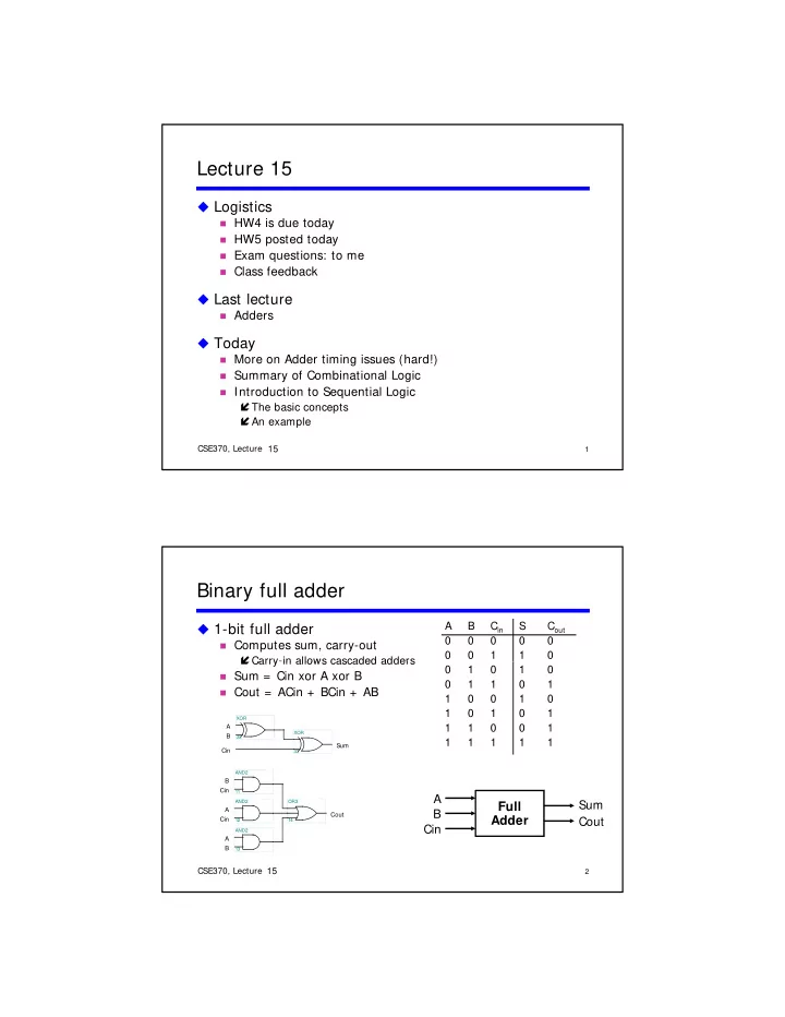
Binary full adder
1-bit full adder
Computes sum, carry-out
Carry-in allows cascaded adders
1 1 1 1 1 1 1 1 1 1 1 1 1 1 1 1 1 1
Carry in allows cascaded adders
Sum = Cin xor A xor B Cout = ACin + BCin + AB
Cin Sum B A
33 XOR 32 XOR AND2
2
CSE370, Lecture 13
A B Cin Cout Sum
Full Adder
A B Cin A Cout Cin B
13 AND2 12 AND2 14 OR3 11
11 15