
SLIDE 1
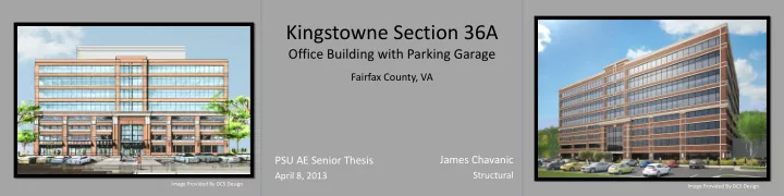
Kingstowne Section 36A
Office Building with Parking Garage
PSU AE Senior Thesis
April 8, 2013
Image Provided By DCS Design Image Provided By DCS Design
Fairfax County, VA
James Chavanic
Structural
Kingstowne Section 36A Office Building with Parking Garage Fairfax - - PowerPoint PPT Presentation
Kingstowne Section 36A Office Building with Parking Garage Fairfax County, VA James Chavanic PSU AE Senior Thesis Structural April 8, 2013 Image Provided By DCS Design Image Provided By DCS Design P RESENTATION O UTLINE BUILDING
April 8, 2013
Image Provided By DCS Design Image Provided By DCS Design
Structural
Image Provided By DCS Design Image Provided By DCS Design
BUILDING OVERVIEW
PROJECT TEAM
Owner: Halle Companies Architect: Davis, Carter, Scott Ltd. (DCS Design) GC: L.F. Jennings Inc. Civil Eng.: Tri-Tek Engineering
Jordan & Skala Engineers
Cagley & Associates
Image From Bing Maps
27’ Difference N
Original Images: DCS Design
ROOF
Original Image: Cagley & Associates
OFFICE LEVELS 2 THROUGH 4
Original Image: Cagley & Associates
PARKING LEVELS AND OL1
Original Image: Cagley & Associates
FOUNDATION
Original Image: Cagley & Associates
SETTING THE STAGE
www.defense.gov www.gsa.gov www.asce.org
BREADTH 1: SITE REDESIGN
BREADTH 2: FACADE REDESIGN
MAE REQUIREMENTS
STRUCTURAL DEPTH
GRAVITY SYSTEM
DESIGN CONSIDERATIONS
DESIGN OF EDGE BEAMS
DESIGN/CHECK OF COLUMNS
WIND LOAD
SEISMIC LOAD
SOIL LOAD
ETABS MODEL
SHEAR WALL DESIGN
SHEAR WALL DESIGN
CHECK ON TYPICAL SPREAD FOOTING
REQUIREMENTS
TIE-FORCE METHOD
ALTERNATE PATH METHOD
ENHANCED LOCAL RESISTANCE
RESULTING DESIGN
SLABS
EDGE BEAMS
COLUMNS
COST COMPARISON
N N
DESIGN PARAMETERS
DESIGN GUIDES
RESULTS
concrete
progressive collapse
ACKNOWLEDGEMENTS
Image Provided By DCS Design