Kilolo Water Project Kilolo Water Project Team Nathaniel Curry - - PowerPoint PPT Presentation

kilolo water project kilolo water project team
SMART_READER_LITE
LIVE PREVIEW

Kilolo Water Project Kilolo Water Project Team Nathaniel Curry - - PowerPoint PPT Presentation

Kilolo Water Project Kilolo Water Project Team Nathaniel Curry Andrea Huelsnitz Brian Givens Katlynn Lawrence Jacob McGowan All Mechanical Engineering Students Important People Sponsors: Tim Edwards Ronald Reed Faculty Advisor: Greg


slide-1
SLIDE 1

Kilolo Water Project

slide-2
SLIDE 2

Kilolo Water Project Team

Nathaniel Curry Brian Givens Andrea Huelsnitz Katlynn Lawrence Jacob McGowan

All Mechanical Engineering Students

slide-3
SLIDE 3

Important People

Sponsors: Tim Edwards Ronald Reed Faculty Advisor: Greg Watkins Ph.D, PE

slide-4
SLIDE 4

The Water Problem

Almost 50% of Tanzanians do not have a clean water well within a half mile of their home.1 Currently there are

  • ther drills on the

market, but they are costly. Our sponsors currently have produced 17 working models.

1 wateraid.org

slide-5
SLIDE 5

Drilling Operation

  • Drilling rig is manufactured

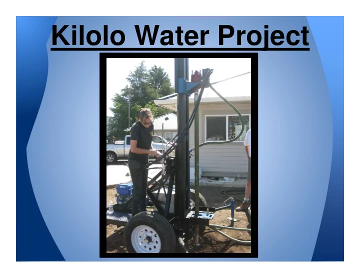
and assembled in Chico (currently)

  • Shipped to Tanzania via

shipping container

  • Average drill depth of 50-80ft
  • Uses a mud rotary drilling

process

  • Drill pipe sections are added

as hole is drilled

  • Drill pipes are removed after

drilling using drilling rig

slide-6
SLIDE 6
slide-7
SLIDE 7

Problem Definition

  • n improved, easy to assemble

drill rig that is reliable and is able to be transported through rough terrain without failure.

  • Original design does not reliably drill

deep enough to reach clean water in certain areas due to adverse soil compositions and inability to reach adequate depths.

  • Original design is too technical for

developing countries to manufacture.

slide-8
SLIDE 8

Must Do

Requirements Engineering Specification Metric Method/ Device Target Condition Easy to Assemble Machine Time to Assemble hr Stop Watch, 4 People 10 Assembled from Parts, No prior experience Maximum Capacity Load Weight Lb. Lift Equivalent Weight of Pipe 1500 Lift the load the full stroke of the cylinder. Prepare for Transport Dimensions Ft. Measuring Tape Max H: 7.5 Max W: 7.6 Current Shipping Method Reliable During Drilling Dimensions Ft. Drill a hole 20 Sandy Loam Standardize Parts and Assemblies

slide-9
SLIDE 9

Should Do

Requirements Engineering Specification Metric Method/ Device Target Condition No Damage During Transportation Speed MPH Simulate by driving over speed bumps 10 No damage that would make it un-operational

  • r transportable

(One trip) Reduce Current Cost Cost $ Total cost of all Materials By 10% Material Availability in Africa Same Torque Force x Length ft-lbs Tachometer Keep Same Unloaded Reduce Operator Work

  • Minimize

Welding

slide-10
SLIDE 10
  • Converted the manual rig to a completely

hydraulic design.

  • Optimized the original hydraulic system to

power both a rotary motor and cylinder.

  • Designed the rig to withstand 2500 lbs
  • Pipe weighs 1500 lbs at 280 ft
  • Drilling conditions add additional

stresses

slide-11
SLIDE 11
slide-12
SLIDE 12

Progression of Design Solution

slide-13
SLIDE 13
slide-14
SLIDE 14
slide-15
SLIDE 15
  • Simple design
  • All steel used for fabrication was

purchased from Pollack Steel

  • Machinery needed:
  • Drill Press
  • Hand Drills
  • Horizontal Band Saw
  • Vertical Band Saw
  • Cut-off Wheel
  • Grinder
  • Welder
  • Fabricators: Dave Lawrence, Katlynn

Lawrence, and Brian Givens

slide-16
SLIDE 16
  • We were given an original rig that we

partially dismantled to have a base for

  • ur rig.
  • Hydraulic cylinder was the only

purchased part that was not already available at the shop.

  • Purchased parts obtained from original

rig:

  • Gasoline engine
  • Hydraulic motor
  • Swivel
  • Hydraulic pump
  • Drill Pipe

Purchased Parts

slide-17
SLIDE 17
  • Design changes to utilize original rig parts:
  • Mast supports 1/4" instead of the design

3/8" thick

  • Gussets and an extra brace were added

to the mast supports for added strength

  • Overall the rig was built how it was

designed at the beginning of this semester.

  • No significant manufacturing difficulties.

Resultant Design Changes

slide-18
SLIDE 18
slide-19
SLIDE 19
  • Tested:
  • No Damage During Transport
  • Prepare for Transport
  • Reliable During Drilling
  • Maximum Capacity Load
  • Specifications That Don't Need Testing
  • Easy to Assemble
  • Same Torque Output
slide-20
SLIDE 20
  • Transportation Test
  • No Damage During Transport
  • Prepare for Transport
  • Lift Test
  • Maximum Capacity Load
  • Hole Completion Test
  • Reliable During Drilling

Tests Performed

slide-21
SLIDE 21
slide-22
SLIDE 22
slide-23
SLIDE 23
  • !"#!$%!&'('
slide-24
SLIDE 24
  • Total Project Funding: &'('
slide-25
SLIDE 25
  • Design Changes for Future Rigs
  • Extend slider length
  • UHMW Teflon inserts on slider
  • Control station offset from drill rig
  • Increase the pump size
  • Sponsors prefer the new rig for drilling

deeper well depths.

  • Merits of new design: drills deeper,

sturdier, safer, stronger, easier to operate.

  • Operation and Assembly manuals make

new design ready for the market.

slide-26
SLIDE 26
  • ))
  • *+%
  • ,-.
  • /0
  • 01
  • R3nown
  • 2!-+3!
  • ,-1%
  • ,/!3%
  • ,,!*
  • 4!,3%

2%%5#!!3%!!5

slide-27
SLIDE 27

Questions