stiffness and strength of laminates fabricated with bi
play

STIFFNESS AND STRENGTH OF LAMINATES FABRICATED WITH BI-DIRECTIONAL - PDF document

18 TH INTERNATIONAL CONFERENCE ON COMPOSITE MATERIALS STIFFNESS AND STRENGTH OF LAMINATES FABRICATED WITH BI-DIRECTIONAL TAPE J. D. D. Melo 1 *, T. K. Parnell 2 , C. A. Tower 3 1 Department of Materials Eng., Federal Univ. of Rio Grande do Norte,


  1. 18 TH INTERNATIONAL CONFERENCE ON COMPOSITE MATERIALS STIFFNESS AND STRENGTH OF LAMINATES FABRICATED WITH BI-DIRECTIONAL TAPE J. D. D. Melo 1 *, T. K. Parnell 2 , C. A. Tower 3 1 Department of Materials Eng., Federal Univ. of Rio Grande do Norte, Natal (RN), Brazil 2 PEC - Parnell Engineering & Consulting, Sunnyvale, CA, USA; & Mechanical Engineering Department, Santa Clara University, Santa Clara, CA, USA 3 Department of Mechanical Engineering, Stanford University, Stanford, CA, USA * Corresponding author (daniel.melo@ufrnet.br) Keywords : Bi-directional tape; tape laying; mechanical properties. [0] plies resulting in an extra 0.5" lip on each side of Abstract In this investigation, the stiffness and the tape that can overlap the adjacent tape, as shown strength of laminates manufactured with bi- in Fig. 1, without any changes in overall ply count. directional pre-preg tape were evaluated. This overlap bridges the discontinuous seam of the [45/0/-45/90] s flat panels were manufactured with off-axis ply. [45/0] IM7/8552 bi-directional pre-preg tape by CNC tape laying. The bi-directional tape under discussion consisted of a 6” wide pre -preg layer of 45 degree fiber with a 5” wide pre -preg layer of 0 degree fiber centered on top of it. The bi- directional tape was laid up in side-by-side passes using an automated tape laying machine. An overlap of 0.5” between adjacent plies was formed to bridge the discontinuous seam of the off-axis ply. Stiffness and strength data of tensile specimens cut from the manufactured panel in various angles were measured and the properties were compared to the same properties of specimens cut from panels with continuous plies. Finite element analyses were conducted to predict the properties of the specimens and the results were found to be in good agreement with the measured properties. The most important Figure 1: Bi-directional tape with 0.5" overlap repeating every 5.5”. Each tape strip is 6.0” wide. advantage of the bi-directional concept presented is the savings in layup time using a tape laying machine. This is achieved by eliminating the need
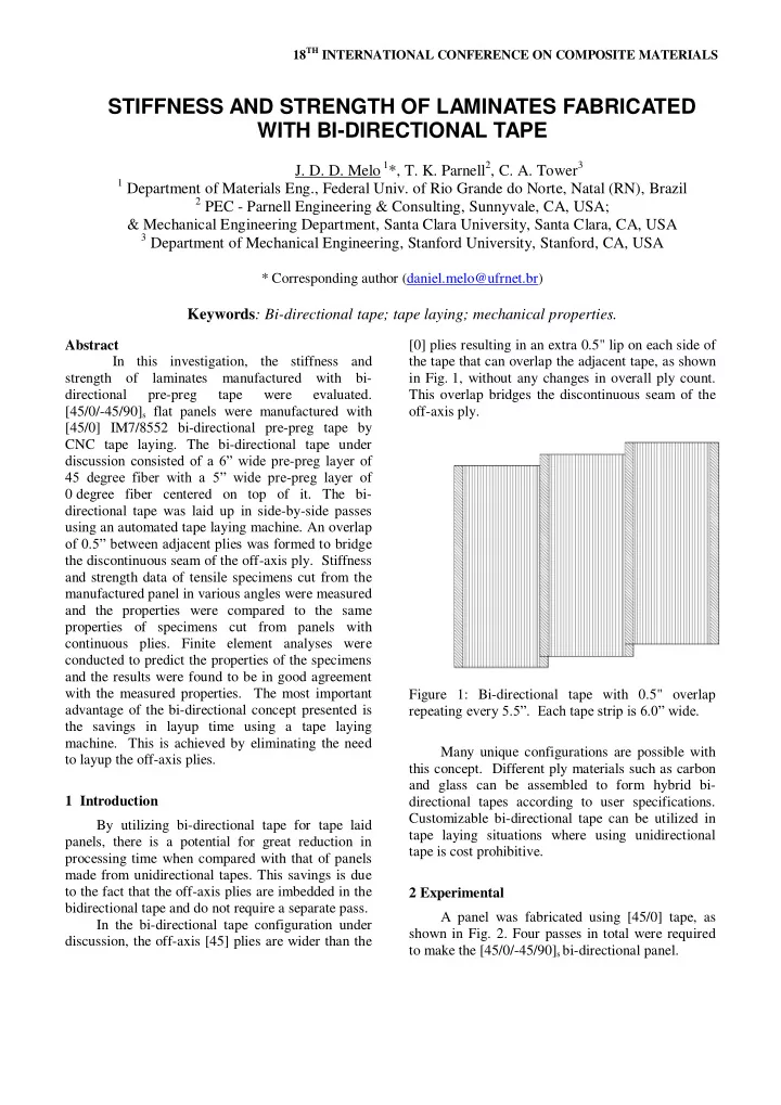
 Many unique configurations are possible with to layup the off-axis plies. this concept. Different ply materials such as carbon and glass can be assembled to form hybrid bi- 1 Introduction directional tapes according to user specifications. Customizable bi-directional tape can be utilized in By utilizing bi-directional tape for tape laid tape laying situations where using unidirectional panels, there is a potential for great reduction in tape is cost prohibitive. processing time when compared with that of panels made from unidirectional tapes. This savings is due to the fact that the off-axis plies are imbedded in the 2 Experimental bidirectional tape and do not require a separate pass. A panel was fabricated using [45/0] tape, as In the bi-directional tape configuration under shown in Fig. 2. Four passes in total were required discussion, the off-axis [45] plies are wider than the to make the [45/0/-45/90] s bi-directional panel.

  2. depending on specimen location within the panel (Fig. 3.b). a) Figure 2: Layup operation using bi-directional tape. b) Figure 3: FEA material groups. a) 50% width soft strip model for a 0 deg orientation specimen. b) 45 A panel was also fabricated using deg orientation specimen with 3 soft-strips along the continuous fibers for baseline comparison. Tensile gage length of the specimen. specimens were cut from both the bi-directional tape laid panel and the continuous panel to investigate the stiffness and strength of bi-directional tape layups The strength data of continuous ply and assess the effect that discontinuous fibers have specimens cut at various orientations are presented on those properties. in Fig. 4, overlaid with the FEA calculated data. Although 0 deg, 45 deg and 90 deg specimens are 1” wide specimens at 5 orientations (0, 90, expected to display the same strength, some 45, 22.5 and 67.5 deg) were water jet cut for tensile variation was observed in the experimental data. testing. The specimens were 10” long providing for a 6” gage length. Specimens wer e pulled to failure and both the initial elastic modulus and the strength were recorded. 3 FEA Simulation Finite element simulations were performed for both the continuous ply specimens and the bi- directional tape specimens. The analysis includes progressive degradation and failure of individual plies to predict the maximum strength [1][2]. The analysis was performed with MSC.MARC 2010 [3] using a 3D shell model with 8 layers. Figure 4: Strength of continuous ply specimens cut at various orientations. (♦) is FEA calculated data. 4 Results In Fig. 5, a drop in strength of the off-angle The 0.5” wide tape overlaps were expected specimens is observed for specimens cut from the to provide a “soft” strip with reduced strength and bi-directional tape panel. This strength reduction is modulus. The specimen area comprised of the soft primarily associated with the fiber discontinuity at strip varied depending on the position and the soft strips and is potentially significant for any orientation of the specimen in the panel. For a 0 deg off-angle orientations (orientations other than 0 deg orientation specimen, the soft strip could comprise a or 90 deg). Fiber discontinuity was modeled as a maximum of 50% of the specimen width (Fig. 3.a). narrow strip of elements where the discontinuous This represents a worst-case condition, as wide layer was given a reduced material modulus panels will have less than 20% of the area with soft equivalent to the modulus of the matrix only (the strips in a given direction. For an off-angle specimen, there can be 2 or 3 soft-strip locations

  3. STIFFNESS AND STRENGTH OF LAMINATES FABRICATED WITH BI-DIRECTIONAL TAPE fiber contribution to the modulus was fully experimental tests showed a 24% strength reduction discounted in the discontinuous region). for the 0 deg orientation specimen with 50% of the specimen width (0.5” out of the 1.0” specim en FEA calculated strength of the 45 deg off- width) taken up by the soft strip (Fig. 6). This is an extreme case, since the laminate will have a 0.5” angle specimens was lower than experimentally wide soft strip for a 5.5” wide overall repeat unit. measured data. This drop may be explained by the number of “soft” strips along the gage length of the specimen. The FEA data presented assumed the In Figs. 7 and 8, the elastic modulus of worst-case situation, corresponding to 3 soft-strips specimens at various angles taken from the along the gage length of the specimen. However, continuous and bi-directional laminates, the specimens tested may have had less than the respectively, are presented. Contrary to its effect on maximum possible soft-strip. A precise assessment strength, the elastic modulus is much less sensitive of the soft-strip percentage was not available for the to the presence of soft strips, assuming the strip is off-angle cases. not oriented along the specimen´s length (Figs. 7 and 8). There was a reduction in elastic modulus for 45 deg specimens of about 10% in predicted data, which was not observed in experimentally measured data (Fig. 8). Again, the off-angle specimens tested may have had less than the maximum possible soft- strip. If the test specimens do actually have less than the maximum amount of soft-strip, the measured modulus should be higher than the FEA modulus prediction. Figure 5: Strength of bi-directional tape specimens cut at various orientations. (♦) is FEA calculated data. Figure 7: Elastic modulus of continuous ply specimens cut at various orientations. (♦) is FEA calculated data. A 17% reduction in elastic modulus was observed for the 0 deg orientation specimen configuration with 50% of the specimen width taken Figure 6: Effect of “soft” strip along the length on up by the soft strip (Fig. 9). Once again, the strength of bi-directional tape specimens . (♦) is FEA reduction in modulus is less significant than the calculated data. reduction in strength. The effect of a soft strip along the length of the specimen is presented in Fig. 6. The 3

Download Presentation
Download Policy: The content available on the website is offered to you 'AS IS' for your personal information and use only. It cannot be commercialized, licensed, or distributed on other websites without prior consent from the author. To download a presentation, simply click this link. If you encounter any difficulties during the download process, it's possible that the publisher has removed the file from their server.

Recommend


More recommend