
SLIDE 1
1
Internet-1
S-38.2121 / Fall-07 / RKa, NB
Introduction to routing in the Internet
Ethernet, switching vs. routing Internet architecture Addressing, routing principles Protocols: IPv4, ICMP, ARP (Chapters 2–3 in Huitema)
Internet-2
S-38.2121 / Fall-07 / RKa, NB
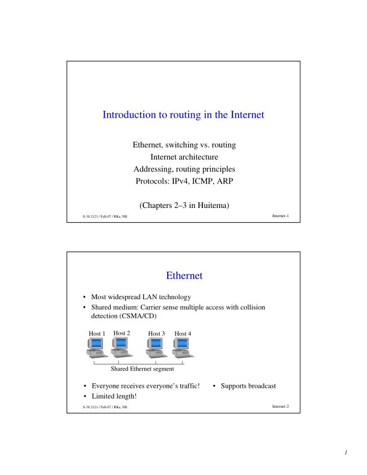
Ethernet
- Most widespread LAN technology
- Shared medium: Carrier sense multiple access with collision
detection (CSMA/CD)
Shared Ethernet segment Host 1 Host 2
- Everyone receives everyone’s traffic!
- Limited length!
Host 3 Host 4
- Supports broadcast