
SLIDE 1
1
Chapter 6 The Data Link layer
6.1 introduction, services 6.2 error detection, 6.5 link virtualization: MPLS 6.6 data center , correction 6.3 multiple access protocols 6.4 LANs
- addressing, ARP
networks 6.7 a day in the life of a web request
(play animation in .ppt slide on your own)
Data Link Layer (SSL) 6-1
addressing, ARP
- Ethernet
- layer-2 switches
- VLANS
y )
12/5/2017
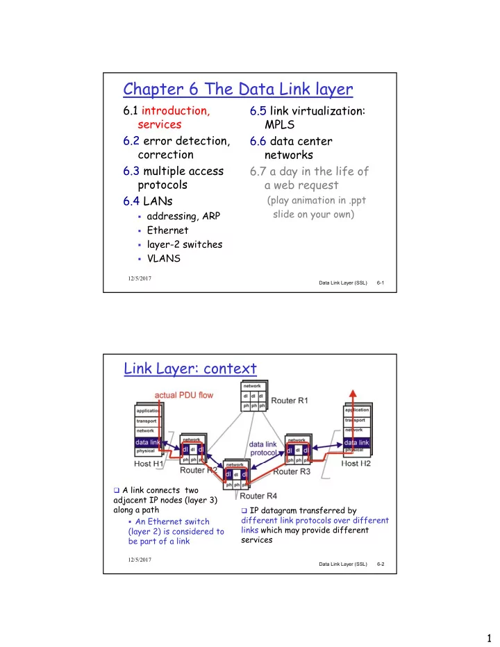
Link Layer: context
A link connects two
adjacent IP nodes (layer 3)
Data Link Layer (SSL) 6-2
adjacent IP nodes (layer 3) along a path
- An Ethernet switch
(layer 2) is considered to be part of a link
IP datagram transferred by
different link protocols over different links which may provide different services
12/5/2017