Integration of Routing and Switching Label Switching & IP - - PDF document

integration of routing and switching
SMART_READER_LITE
LIVE PREVIEW

Integration of Routing and Switching Label Switching & IP - - PDF document

Integration of Routing and Switching Label Switching & IP switching The goal is to avoid executing packet forwarding algorithm for each and every packet and replace it with switching in hardware. The result is faster and less expensive IP


slide-1
SLIDE 1

S38.121/RKa s-01 7-1

Integration of Routing and Switching

Label Switching & IP switching

The goal is to avoid executing packet forwarding algorithm for each and every packet and replace it with switching in hardware. The result is faster and less expensive IP network with Integrated Traffic Engineering Mechanisms.

  • Motivation
  • History
  • Principle of Label swapping and its properties (MPLS)
  • Label Distribution Protocol
  • Traffic management and MPLS

LUE uudet specsit!

S38.121/RKa s-01 7-2

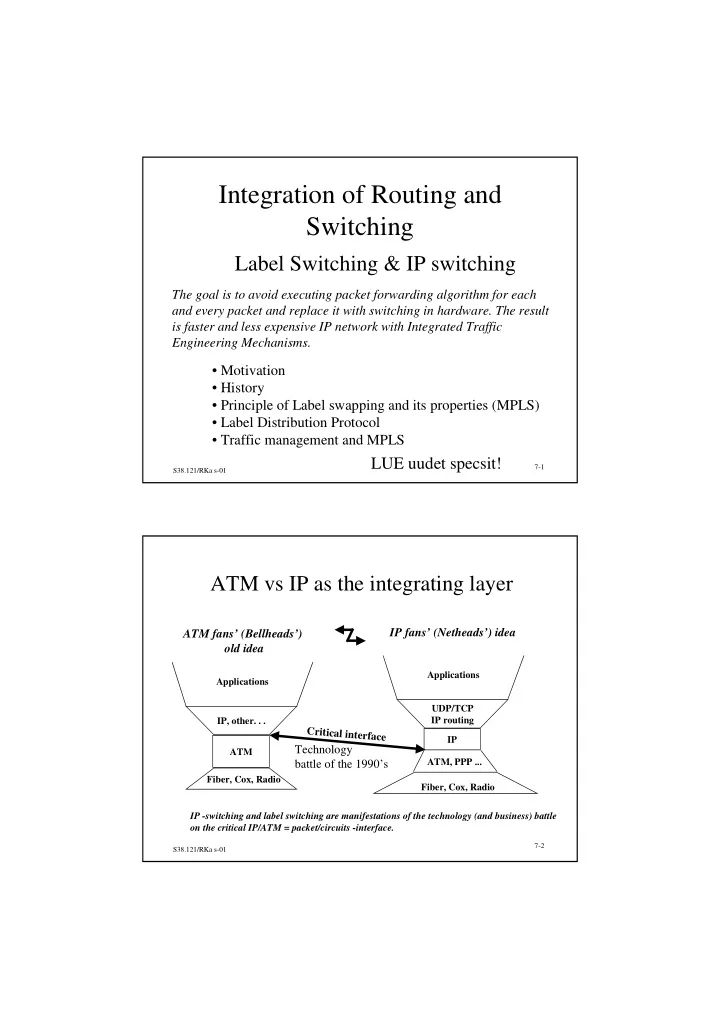
ATM vs IP as the integrating layer

ATM IP, other. . . Fiber, Cox, Radio Applications

ATM fans’ (Bellheads’)

  • ld idea

IP UDP/TCP IP routing Fiber, Cox, Radio Applications ATM, PPP ...

IP fans’ (Netheads’) idea

Critical interface

IP -switching and label switching are manifestations of the technology (and business) battle

  • n the critical IP/ATM = packet/circuits -interface.

Technology battle of the 1990’s

slide-2
SLIDE 2

S38.121/RKa s-01 7-3

Basic problem of all IP over ATM solutions is the huge nrof flows and their small size

  • A Flow is a sequence of packets from a source address or

prefix to a destination address or prefix possibly with a certain UDP/TCP source and destination ports. Cmp. packets sent in a TCP-session.

  • Average length of a flow in the Internet seems to be < 10 000
  • ctets
  • On 1 Gbit/s wirespeed we have

– 12500 = nrof flows that are created and disappear each second – 450 M flows created and disappear/h in a router with 10 ports – 100…1000 -fold too much for each flow to be treated like a “phone call”.

S38.121/RKa s-01 7-4

Many attempts to adapt IP to underlaying ATM

  • Classical IP over ATM
  • LANE - LAN Emulation
  • MPOA = LANE extended to WAN (wide area)

– destinations far away in an ATM network can be attached into an IP network by establishing virtual connections to them (=by making an “ATM-call”) based on traffic or connectivity needs All these architectures suffer from Complex Architecture, in-efficiency and poor scalability.

slide-3
SLIDE 3

S38.121/RKa s-01 7-5

What’s wrong in a pure IP network?

  • Can not guarantee or even assure Quality of Service.
  • Packet forwarding with longest match destination

prefix search is a rather slow operation

– can be turbo-charged with HW but the question of adaptability to protocol changes remains

  • Routing based on Shortest Paths Only limits
  • perator’s capability to manage the traffic in the

network and use network resources efficiently

– Because there is no route pin-down, it is difficult to implement alternative routing.

S38.121/RKa s-01 7-6

Routing and switching are mechanisms for mapping traffic to network resources

Slow Fast Datagrams IP switching Label switching Routing Internet model Routing PVC SVC “call” Telephony model Handover s w i t c h i n g

Initial GOAL was switching performance optimization from a node point of view.

slide-4
SLIDE 4

S38.121/RKa s-01 7-7

IP switching reduces router load by connecting part of the traffic directly thru the ATM fabric

ATM Fabric Flow classification Forwarding

L3 L2 L1 OSI default-vci 1 1 2b IFMP redirect 2a 3

Per-flow vci

4b IFMP redirect 4a 5

  • 1. IP switches work as routers. IP-packets are carried on the default VCI.

In addition the node run the Flow Classification program.

  • 2. Flow Classifier has detected a flow, 2a - IP-switch reserves a dedicated upstream VCI for

the flow. 2b - IP switch sends IFMP redirect message to upstream neighbor.

  • 3. Upstream IFMP-node starts forwarding remaining packets of the flow onto that VCI.

The first packet on the VCI acts as an acknowledgement to IFMP redirect message.

  • 4. Downstream IP-switch/router has also detected the flow and sends a redirect message.
  • 5. IP-switch thruconnects the flow in the ATM Fabric (Processor is out of loop).

Upstream Downstream IP-switch

S38.121/RKa s-01 7-8

Properties of IP switching (a’ la IPSILON)

  • Several flow types

– source IP-address, destination-IP-address + many packets – source IP-address, destination-IP address, TCP/UDP-ports

  • Flow packets have their own encapsulation
  • Last downstream IFMP -node which pops the packet to its

processor, sets the packet TTL to the right value.

  • IP -switching is a traffic driven end-to-end solution
  • Approximately 70 - 80% of packets can be mapped to flows

and switched

slide-5
SLIDE 5

S38.121/RKa s-01 7-9

IP switching by IPSILON forced forward several competing solutions

  • Cisco:

Tag Switching

  • IBM:

ARIS - Aggregate route based IP switching

  • Toshiba: CSR - Cell switch router
  • Juha Heinänen: SITA - Switching IP through ATM

Added value is topology driven switching - whole routes are mapped to virtual paths/circuits in the underlaying link layer. IETF started to create order in chaos with its - MPLS - MultiProtocol Label Switching activity.

S38.121/RKa s-01 7-10

In topology driven Label Switching a full mesh VCC network is established on a Label Switched Domain

Label Switch - LS LR Label Router - LR Ingress LR adds a Label before the packet LS LS swaps incoming label to outgoing label i.e. performs switching

  • n layer 2.

Egress LR removes Label before the packet TDP/LDP Label Switched Path

slide-6
SLIDE 6

S38.121/RKa s-01 7-11

A Label Switched network in action: phase 1

1. Label Routers and Label Switches work as any Router (as OSPF, BGP, etc protocol nodes) - we call them Label Switching Routers.

Std Routing Table OSPF, BGP ... OSPF, BGP ... Std Routing Table Std Routing Table

S38.121/RKa s-01 7-12

A Label Switched network in action: phase 2

  • 2. LR and LS ( or LSR)
  • use the Routing Table created normally by routing protocols to set

labels

  • distribute labels using routing, RSVP or LDP -protocols.
  • LR builds Label Information Base from received info.

LDP/OSPF/BGP/RSVP LDP ...

Std Routing Table label

LIB LIB LIB

  • MPLS group has published a DRAFT LDP spec ( last 10/99?).

Std Routing Table label Std Routing Table label

slide-7
SLIDE 7

S38.121/RKa s-01 7-13

Label Switched network in action: ph. 3

  • 3. When Ingress-LR receives a packet from outside the LS-Domain,
  • it analyses the packet header, performs layer 3 services,
  • fetches outgoing interface from Routing Table and Label from LIB,
  • adds Label prior to packet header and send the packet to next LS.

LIB LIB LIB

IP packet on default VCI IP packet VPI/VCI=label Std Routing Table label Std Routing Table label Std Routing Table label

S38.121/RKa s-01 7-14

Label Switched network in action: ph. 4, 5

  • 4. LS receives Label packet on layer 2, swaps incoming to outgoing Label

and sends the packet to outgoing interface.

  • 5. Egress LR removes label from packet and routes the packet based on

IP packet header.

LIB LIB LIB

IP packet VPI/VCI=new label

LIB LIB LIB

IP packet VPI/VCI=label IP packet default VCI Std Routing Table label Std Routing Table label Std Routing Table label IP packet VPI/VCI=label Std Routing Table label Std Routing Table label Std Routing Table label

slide-8
SLIDE 8

S38.121/RKa s-01 7-15

Many transport mechanisms for Labels are specified - Label Switching is independent of MAC -layer

Label can be transported:

  • as part of MAC header (e.g. ATM VPI/VCI)
  • as part of network layer header (flow label in IPv6)
  • in the header of a new “shim” layer between MAC-layer

and network layer: In fact this is the method used in European pilot deployments!

Efficient manipulation of Labels requires HW-support of Label Switching:

  • In ATM label switching = ATM-switching in ATM fabric.

S38.121/RKa s-01 7-16

Labels may be bound to packets based on many criteria

  • A Label may be bound (by LDP) with a set of IP

addresses called FEC - Forwarding Equivalence Class.

– All packets in one FEC receive the same MPLS treatment – A FEC can be, for example, an IP address prefix (0…32 bits). – A FEC can be also IP address of a Host (this has higher priority) – ( also proposed: FEC is a multicast -address and Label is associated with a multicast tree)

  • We talk about Flow Granularity.
slide-9
SLIDE 9

S38.121/RKa s-01 7-17

Tables in a Label Switch are

Routing Table Prefix Next hop Label prefix1 . . . prefixn Node 1 . . . Node m Label 1 . . . Label p Label Information Base (LIB)/node or/incoming port) incoming Next hop label label1 . . . labelp Node 1 . . . Node m Label y . . . Label x Outgoing label

  • utgoing-MAC-add

If outgoing label = VCI, LIB entry will also carry TTL-decrement = length of Label Switched Path (nrof of hops), so that TTL can be set to the right value prior to sending in the ingress router.

S38.121/RKa s-01 7-18

Label allocation mode can be Downstream on- demand or Unsolicited Downstream

Routing Table Prefix Next hop Label prefix1 . . . prefixn Node 1 . . . Node m Label 1 . . . Label p An entry is created in LIB, incoming label is inserted. LIB Incoming Next hop Label Outgoing label

  • utg-MAC-add

Label 1 . . . Label p Node 1 . . . Node m Label x . . . Label y Upstream 3 Advertise Label association with the route to all neighbors. 4 Label Information Base (LIB) Outgoing label

  • utg-MAC-add

Node 1 . . . Node m Label x . . . Label y Next hop An Incoming label is allocated to each (route) prefix. The Label is written in Routing Table. If label advertisement was received from next-hop node, write label as outgoing label for the route

This is Unsolicited Downstream Label Advertisement These a ways to advertise labels

2 1

slide-10
SLIDE 10

S38.121/RKa s-01 7-19

Routing Table Prefix Next hop Label prefix1 . . . prefixn Node 1 . . . Node m Label 1 . . . Label p LIB Incoming Next hop Label Outgoing label

  • utg-MAC-add

Label 1 . . . Label p Node 1 . . . Node m Label x . . . Label y Label Information Base (LIB) Outgoing label

  • utg-MAC-add

Node 1 . . . Node m Label x . . . Label y Next hop

On-demand Label Allocation in action:

1 Next- hop creates an entry in LIB, writes down allocated incoming label. 2 Upstream Node 3 Next-hop advertises upstream the association of the route with the label. 4 Routing Table Prefix Next hop Label prefix1 . . . prefixn Node 1 . . . Node m Label 1 . . . Labelp For each (route) prefix, node requests a label from next-hop node.

Downstream-on-demand label advertisement

If label advertisement was received from next-hop node, write label as outgoing label

  • f the route.

S38.121/RKa s-01 7-20

Two modes of Label Switched Path control in a network

  • Independent LSP Control Mapping: advertise when

– for each new FEC in FIB, when advertisement arrives unsolicited from downstream – Upstream LR sends Label Request about known FEC – next hop of FEC changes and loop prevention is on – attributes of the label switched path change – reception from downstream AND ( upstream label has not been allocated

  • r loop prevention or attributes of LSP have changed)
  • Ordered LSP Control Mapping - is the alternative
  • -> Nodes work autonomously and label binding

progresses as a random process

slide-11
SLIDE 11

S38.121/RKa s-01 7-21

Ordered LSP Control Mapping - Label binding is always initiated by Egress node

  • Downstream LR advertises, when one of the following

conditions is satisfied:

– Egress node of a FEC detects a new FEC – Upstream node sends request about known FEC and LR is the egress of that FEC or it has already set the downstream label – Next hop of FEC changes and Loop prevention is on – LSP attributes change – A label advertisement arrives from downstream AND ( a) upstream label has not been set OR b) loop prevention is on OR c) LSP attributes have changed)

S38.121/RKa s-01 7-22

Label Retention modes

  • Conservative Label Retention Mode

– If labels are distributed unsolicited, they may arrive from many neighbors for a particular FEC. Only the label received from next hop

  • f that FEC is retained

– saves label space, but slows down recovery when route is changed

  • Liberal Label Retention Mode

– labels received from any neighbor are retained. In on-demand mode, more labels may be requested than actually are needed right now – speeds up route recovery but consumes label space

slide-12
SLIDE 12

S38.121/RKa s-01 7-23

Route selection in an MPLS network can be hop-by-hop or explicit

MPLS architecture supports

  • 1. hop-by-hop routing - traditional for packet networks
  • 2. Explicit routing: Ingress or Egress node of the MPLS domain computes

the route thru the domain e.g. based on configuration (policy)

  • r network state information.
  • 3. Explicit routes require new label bindings and distribution.

If explicit route is based on state information (e.g. a-la PNNI), the result is adaptive routing.

  • 4. An LSP is built either hop-by-hop or explicitly.

Mixed paths can lead to loops and therefore not supported.

S38.121/RKa s-01 7-24

Label Distribution Protocol (LDP) is one of methods to distribute, request and release labels

  • Many network protocols are supported (IPv4, IPv6, IPX ...)
  • LDP opens, monitors and closes TCP-sessions dynamically between

peer LSR - Label Switching Routers.

  • One LDP session corresponds to one TCP -session. An LDP-session

is responsible for a certain label space.

  • LDP is symmetric. Label information may be distributed in both

directions. http://www.ietf.org/rfc/rfc3036.txt (2001)

UUSI: LUE

slide-13
SLIDE 13

S38.121/RKa s-01 7-25

LDP maintains a dynamic VCC configuration for optimization of routing

  • LDP session has a keep-alive timer.
  • LDP-session is closed if label information is not received during

keep-alive time.

  • When session is closed, all labels with that peer are released.
  • Alternatives to LDP are
  • label carriage in routing protocol (OSPF, BGP) messages
  • RSVP - Resource reSerVation Protocol

S38.121/RKa s-01 7-26

LDP runs mainly on TCP between peer nodes

  • Peers are detected by sending Discovery message on

UDP to “allRouters in sub-net” -address to find all immediate neighbor peers OR by sending the message to a known IP address of an LSR

– in the latter case the peer is an LSR farther away in the network to which a nested LSP will be set up.

  • All other messages are sent over TCP
slide-14
SLIDE 14

S38.121/RKa s-01 7-27

LDP state machine

Initialized Operational Initialisointi

/Initialization msg Initialization msg (Passive role)/ Init msg and KeepAlive msg KEEP_ALIVE Initialization msg/ KEEP_ALIVE Shutdown msg or Timeout/Shutdown msg On arrows /a = sending of a Other Msg This is the label exchange state

TCP session

(active role)

Non-existent

ANY OTHER/ NAK ANY OTHER/ NAK

Openrec Opensent

S38.121/RKa s-01 7-28

LDP messages carry TLV info elements

LDP_identification contains: sender’s (router-id) IP-address + number of LDP instance in the LSR (2 bytes). The latter uniquely identifies the label space of the sender.

Version = 1 PDU LENGTH (<4096)

4 octets LDP_IDENTIFICATION

LDP header

Type LENGTH (= tlv - 4)

4 octets VALUE ( nrof octets given in LENGTH)

TLV structure

T - Type, L - Length, V- Value Value may carry other TLV structs

UF U - Unknown TLV: 0 - Notify originator; Ignore entire msg; 1 - ignore this TLV F - Forward unknown TLV-bit: U=1,F=1 --> unknown TLV is forwarded

slide-15
SLIDE 15

S38.121/RKa s-01 7-29

Example LDP message

Version = 1 LENGTH = 25

4 octets LDP_IDENTIFICATION

Type LENGTH = 6 Type LENGTH = 5 Value

Value There are some exceptions to the TLV style

  • f coding all information for achieving more

compact coding.

S38.121/RKa s-01 7-30

FEC - Forwarding Equivalence Class TLV

(FEC) 0x0100 00 Length FEC Element 1 . . . FEC Element n

FEC Element Types: Wild Card 0x01 - Label withdraw, release Prefix 0x02 - Address prefix Host Addr 0x03 - IP address of a Host Gen Label 0x0200 00 Length Label

Label can in practice be e.g. in ATM: VPI+VCI (12+16 bits)

  • r FR DLCI (10, 17 or 23 bit)
slide-16
SLIDE 16

S38.121/RKa s-01 7-31

LDP message types are

Notification

  • Serious and non-serious errors

Hello

  • Maintenance of peer relationships

( Immediate and addressed neighbors) Initialization

  • Initialization of an LDP session

KeepAlive

  • Refreshing the session

Address

  • Contains LSR I/f address list

Address Withdraw

  • To withdraw an advertisement

Label Mapping

  • Setting up label bindings

Label Request

  • Requesting labels from downstream

Label Abort Request - Request to abort a pending request Label Withdraw

  • to Break binding between labels and FECs

Label Release

  • To release labels previously requested or

received

S38.121/RKa s-01 7-32

Traffic driven vs. topology driven packet switching

Traffic driven

  • end-to-end hop-by-hop solution
  • scalability for Internet backbone =?

reason: millions of flows/link

  • policy based QoS for a small part of

the traffic seems easy to add

Topology driven

  • label domain wide hop-by-hop and

explicit routing and traffic management solution

  • label and routing properties are

background operations as compared to user traffic => layer 2 determines top performance

  • How large can a label switched

domain really be? Independent of ATM - both approaches are possible also directly on top of Packets-over-Sonet (POS) - this leads to new kind of label switching hardware. How easy is it to add QoS support in to MPLS networks?

slide-17
SLIDE 17

S38.121/RKa s-01 7-33

Issue 1: On an LSP Virtual Paths to destination need to merge

LSR LSR LSR VP=7 VP=5 4 4 4 8 8 8 LSR VP=9 4 8 8 8 4 4 4 1 2 3 Input Input Output Output Port VP Port VP 1 7 3 9 2 5 3 9 Downstream Upstream ATM-cells: VPI/VCI=7/4

S38.121/RKa s-01 7-34

Merging virtual paths will reduce the use

  • f label space and nrof LSPs

A D C B E F

N x (N-1) -paths N = nrof routes

A D C B E F

O(N) mpt-to-pt paths. Scales better VPI- space is streched for a larger domain

VC merge

VC - virtual connection (“ATM-call”)

slide-18
SLIDE 18

S38.121/RKa s-01 7-35

Routing loops in a label switched network need to be either detected or prevented

  • Label paths follow routing information produced by IP routing.
  • If loops are possible on IP-layer, the same applies to label

switching layer.

  • Counter measures are needed:
  • Path vector (LDP-message route) can be transferred

in LDP messages

S38.121/RKa s-01 7-36

Traffic management requirements for MPLS

RFC 2702: “Requirements for Traffic Engineering over MPLS”, 28 s, 9/99. Traffic Engineering (TE) is concerned with performance optimization

  • f operational networks. TE encompasses the application of technology

and scientific principles to the measurement, modeling, characterization and control of Internet traffic and the application of such knowledge and techniques to achieve specific performance objectives. Measurement and Control are the aspects of TE that concern MPLS.

slide-19
SLIDE 19

S38.121/RKa s-01 7-37

Performance Objectives or traffic management are divided

  • Traffic oriented

– improve quality of service offered to traffic streams – reduce packet loss, delay, jitter – maximization of traffic carried by the network – fulfillment of Service Level Agreements (SLA)

  • Resource oriented

– optimization of resource usage – avoiding overload in one part of the network while another part of the network is lightly loaded - when traffic matrix and network dimensioning do not match well.

S38.121/RKa s-01 7-38

Traffic management model in MPLS

LSR LSR LSR LSR LSR LSR LSR LSR LSR LSR LSR MPLS- network Network configuration management tools Control Policy Network performance measurement system Control can be based either on predicted traffic or real-time measurement.

slide-20
SLIDE 20

S38.121/RKa s-01 7-39

Shortest path routing can cause traffic management problems

  • Shortest paths of too many traffic streams can merge
  • n a single link or on a single router interface
  • Offered traffic or traffic demand on a link can be

larger than link capacity

  • at the same time, it is possible that there is a feasible

alternative route for the excess traffic so that the demand could be met.

S38.121/RKa s-01 7-40

Benefits of IP over ATM and FR include

  • In FR and ATM -networks it is possible to set up an

arbitrary logical topology that is shown to IP-routing layer

– Constraint based routing at the VC -level – Operator configured static virtual paths – Minimization of nrof hops seen by IP routing – CAC - call admission control – traffic shaping and restriction – connection recovery (survivability) at VC layer

slide-21
SLIDE 21

S38.121/RKa s-01 7-41

MPLS target model for traffic management

Management Interface of the Operator Link state database Resource Attribute Availability DB MPLS Normal Interior routing Constrained based routing process

S38.121/RKa s-01 7-42

MPLS terminology for traffic management

  • Traffic trunk - aggregation of traffic flows of the same class

which are placed inside a Label Switched Path

– object for routing – LSP + attributes

  • Induced MPLS-graph (leimapolkugraafi)=H = (U, F, d ),

where U ⊆ V - subset of set of all nodes in the network such that u {u ∈ U} has at least one LSP, F - set of LSPs and “d” - set of demands and constraints on LSPs

slide-22
SLIDE 22

S38.121/RKa s-01 7-43

Attractiveness of MPLS from the traffic management point of view is based on

  • Explicit non-shortest path routes are easy to create and

maintain manually or using a protocol

  • traffic trunks are easy to map to LSPs
  • traffic trunks and resources can be described using dynamic

attributes - resource attributes constrain the routing of traffic trunks

  • traffic streams can be merged and split
  • IP-routing+MPLS is simpler (?) for an Operator than IP +

independent underlaying ATM or FR network

S38.121/RKa s-01 7-44

MPLS traffic management mechanisms

Packets FECs

Forwarding Eq Classes

Traffic trunks LSPs

label switched paths

  • Establish
  • Activate
  • Deactivate
  • Modify Attributes
  • Reroute
  • Destroy
  • ( Policing and traffic shaping)

Traffic measurement& statistics

slide-23
SLIDE 23

S38.121/RKa s-01 7-45

MPLS summary

  • Specification takes a long time. MPLS -group has

produced 11 RFCs and 26 Internet Drafts. (Network WG) -another group has produced RFC:n (RFC 2702).

  • IPR may slow progress, QoS =?
  • Motivation of the work has changed on the way

– current motivation is enriching routing capabilities and achieving better traffic management in a unified way – setting up secure VPNs (virtual networks) using MPLS is also an important goal