
SLIDE 1
BRS07 1
www.sorin-schwartz.com
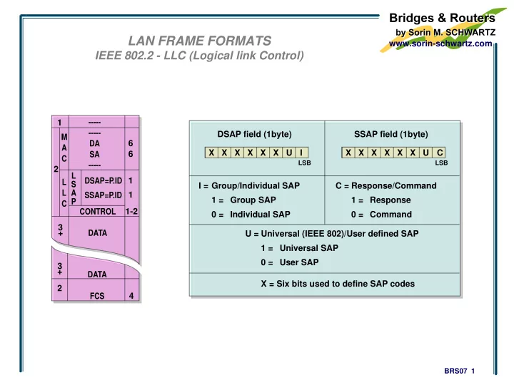
LAN FRAME FORMATS
IEEE 802.2 - LLC (Logical link Control)
DSAP field (1byte) X
LSB
X X X X X U I SSAP field (1byte) X
LSB
X X X X X U C Group/Individual SAP 1 = 0 = I = Group SAP Individual SAP Response/Command 1 = 0 = C = Response Command Universal (IEEE 802)/User defined SAP 1 = 0 = U = Universal SAP User SAP X = Six bits used to define SAP codes
- DA
SA
- 2