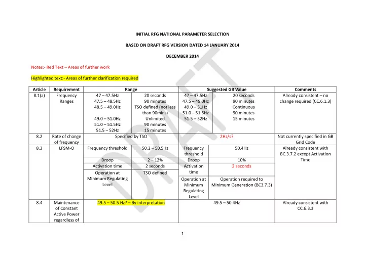
initial rfg national parameter selection based on draft
play

INITIAL RFG NATIONAL PARAMETER SELECTION BASED ON DRAFT RFG VERSION - PowerPoint PPT Presentation

INITIAL RFG NATIONAL PARAMETER SELECTION BASED ON DRAFT RFG VERSION DATED 14 JANUARY 2014 DECEMBER 2014 Notes:- Red Text Areas of further work Highlighted text:- Areas of further clarification required Article Requirement Range Suggested


  1. INITIAL RFG NATIONAL PARAMETER SELECTION BASED ON DRAFT RFG VERSION DATED 14 JANUARY 2014 DECEMBER 2014 Notes:- Red Text – Areas of further work Highlighted text:- Areas of further clarification required Article Requirement Range Suggested GB Value Comments 8.1(a) Frequency 47 – 47.5Hz 20 seconds 47 – 47.5Hz 20 seconds Already consistent – no Ranges 47.5 – 48.5Hz 90 minutes 47.5 – 49.0Hz 90 minutes change required (CC.6.1.3) 48.5 – 49.0Hz TSO defined (not less 49.0 – 51Hz Continuous than 90mins) 51.0 – 51.5Hz 90 minutes 49.0 – 51.0Hz Unlimited 51.5 – 52Hz 15 minutes 51.0 – 51.5Hz 90 minutes 51.5 – 52Hz 15 minutes 8.2 Rate of change Specified by TSO 2Hz/s? Not currently specified in GB of frequency Grid Code 8.3 LFSM-O Frequency threshold 50.2 – 50.5Hz Frequency 50.4Hz Already consistent with threshold BC.3.7.2 except Activation Time Droop 2 – 12% Droop 10% Activation time 2 seconds Activation 2 seconds time Operation at TSO defined Minimum Regulating Operation at Operation required to Level Minimum Minimum Generation (BC3.7.3) Regulating Level 8.4 Maintenance 49.5 – 50.5 Hz? – By interpretation 49.5 – 50.4Hz Already consistent with of Constant CC.6.3.3 Active Power regardless of 1

  2. Article Requirement Range Suggested GB Value Comments changes in System Frequency 8.5 Power Output Below 49Hz falling by a reduction rate of 2% of Power Output should not drop by more than Already consistent with with Falling the Maximum Capacity at 50Hz per 1Hz prorata with frequency (ie maximum CC.6.3.3 Frequency Frequency drop permitted requirement is 100% power at Below 49.5Hz by a reduction rate of 10% of 49.5Hz falling linearly to 95% at 47.0Hz) the maximum Capacity at 50Hz per 1Hz Frequency drop Type B 9.3 Fault Ride U ret :- 0.05 – 0.3 t clear :- 0.14 – 0.15 U ret :- 0.25 t clear :- 0.14 Substantial study work and Through U clear :- 0.7 – 0.9 t rec1 :- t clear U clear :- 0.7 t rec1 :- 0.14 DNO input required (Synch) U rec1 :- U clear trec2:- t rec1 – 0.7 U rec1 :- 0.7 trec2:- 0.45? U rec2 :- 0.85 – 0.9 and trec3:- t rec2 – 1.5 U rec2 :- 0.85 trec3:- 1.5 ≥U clear 9.3 Fault Ride U ret :- 0.05 – 0.15 t clear :- 0.14 – 0.15 U ret :- 0.15 t clear :- 0.14 Substantial study work and Through U clear :- U ret – 0.15 t rec1 :- t clear U clear :- 0.15 t rec1 :- 0.14 DNO input required (would (Asynch) U rec1 :- U clear t rec2 :- t rec1 U rec1 :- 0.15 t rec2 :- 0.14 suggest the same values as U rec2 :- 0.85 t rec3 :- 1.5 – 3.0 U rec2 :- 0.85 t rec3 :- 3.0? current GB Offshore requirements) Type C 10.2(b) LFSM-U Frequency Threshold 49.8 – 49.5Hz Frequency Threshold 49.5Hz This is a new requirement Droop 2 – 12% Droop 10%? and new to the GB Grid Activation Time 2 s Activation Time 2 s Code. Initial values based on FSM Mode of Operation. 10.2(c) FSM Active Power range ıΔP 1 ı/P max 1.5 – 10% Active Power range ıΔP 1 ı/P max 10% Frequency Response Frequency Insensitivity ıΔf i ı 10 – 30mHz Frequency Insensitivity ıΔf i ı ±15mHz Insensitivity is not currently Frequency Insensitivity ıΔf i ı /f n 0.02 – 0.06% Frequency Insensitivity ıΔf i ı /f n ±0.03% used in GB. Deadband 0-500mHz Deadband ±15mHz There is an issue as to how Droop 2 – 12% Droop 3 – 5% Primary and Secondary Maximum admissible delay t 1 2 s Maximum admissible delay t 1 for 2 s Response is defined. There for Generation with Inertia Generation with Inertia only appears to be one 2

  3. Article Requirement Range Suggested GB Value Comments Maximum admissible delay t 1 TSO defined Maximum admissible delay t 1 for TBC? option of low frequency for Generation without Inertia Generation without Inertia response in GB. Activation time t2 30 s Activation time t2 10s 10.2(f) ASBMON Status Signal (on/off) Status Signal (on/off) Changes required to Scheduled Active Power output Scheduled Active Power output NGTS3.24.95 /RES Actual value of Active Power output Actual value of Active Power output Actual parameter settings for Active Power Actual parameter settings for Active Power Frequency Response Frequency Response Droop and deadband Droop and deadband 10.6(b) DSM / Fault Voltage Voltage Changes required to Recording Active Power Active Power NGTS3.24.70 /RES. No Reactive Power Reactive Power reference to Breaker Status Frequency Frequency Type D 11.2(a)( Voltage Range 0.9 – 1.10 p.u Unlimited 0.9 – 1.10p.u Unlimited (275 and 132kV) Narrower bands do not 1) 110kV – 300kV 0.94 – 1.06p.u Below 132kV appear to be permitted Table 6.1 11.2(a)( Voltage Range 0.9 – 1.05 p.u Unlimited 0.9 – 1.05p.u Unlimited at 400kV 1) 300kV – 400kV 1.05 – 1.10 p.u 15 minutes 1.05 - 1.1p.u 15 minutes at 400kV Table 6.2 11.3 Fault Ride U ret :- 0 t clear :- 0.14 – 0.15 U ret :- 0 t clear :- 0.14 Further assessment Through U clear :- 0.25 t rec1 :- t clear – 0.45 U clear :- 0.25 t rec1 :- 0.14 required. RfG only requires (Synchronous) U rec1 :- 0.5 – 0.7 trec2:- t rec1 – 0.7 U rec1 :- 0.5 trec2:- 0.45 resilience against secured (Table 7.1) U rec2 :- 0.85 – 0.9 trec3:- t rec2 – 1.5 U rec2 :- 0.85 trec3:- 0.884 faults whilst GB requires resilience against both secured and unsecured faults. This issue is being addressed through the fault ride through working group. 11.3 Fault Ride U ret :- 0 t clear :- 0.14 – 0.15 U ret :- 0 t clear :- 0.14 Substantial study work and 3

  4. Article Requirement Range Suggested GB Value Comments Through U clear :- U ret t rec1 :- t clear U clear :- 0 t rec1 :- 0.14 DNO input required (Asynchronous U rec1 :- U clear t rec2 :- t rec1 U rec1 :- 0 t rec2 :- 0.14 ) U rec2 :- 0.85 t rec3 :- 1.5 – 3.0 U rec2 :- 0.85 t rec3 :- 1.5 (Table 7.2) Type B Synch 12.3 Fault Ride TSO specified 0.5 seconds Through Active Power Recovery Type C Synch 13.2(b) Reactive In accordance with U-Q/P max profile of Figure 7 RfG requirements are very Power and Table 8 different to GB. GB requires Capability at Maximum range of Q/P max – 0.95 Maximum range of Q/P max – 0.95 0.85pf lag to 0.95 pf lead at Maximum Max range of steady state voltage 0.1p.u Max range of steady state voltage 0.1p.u the Generator unit Capacity terminals. RfG requires Q/Pmax range of 0.95 at the Connection Point. This equates to 0.9 pf lead to 0.9 pf lag at the connection point and a full reactive delivery over a system voltage range of 0.95 – 1.05 p.u. 13.2(c) Reactive Operation required in every possible point in Operation expected to be within the Operating Power the P-Q Capability Diagram of the alternator Chart as defined under OC2 of the Grid Code Capability down to the Minimum Stable Operating Level below Maximum Capacity Type D 4

  5. Article Requirement Range Suggested GB Value Comments Synch 14.2(b) Specifications Specified by RNO and TSO – No ranges given As per CC.A.6 of the Grid Code Check Overexcitation limiter and Bandwidth Limitation Stator Current Limits may be an issue and Stator Current Limiter performance Underexcitation Limiter requirements requirements of AVR and Overexcitation limiter requirements Excitation Stator Current Limiter System Power System Stabiliser requirements Type B PPM’s 15.2(b) Fast Fault Specified by RNO and TSO To be determined This requirement is much Current Requirements for fast fault current either at Current GB requirement states each Power more detailed than currently Injection the Connection Point or Turbine Terminals Park Module should generate maximum specified in CC.6.3.15 of the Criteria for determination of voltage deviation reactive current without exceeding the Grid Code. Requires The characteristics of Fast Fault Current transient rating of the generating unit during extensive analysis and The timing and accuracy of the fast fault the period of the fault modelling work. current which may include several stages Fast Fault current injection for asymmetrical faults 15.3 Post Fault Specified by TSO Specifications and requirements are new to GB This requirement is much Active Power When the post fault active power recovery Grid Code. more detailed than currently Recovery begins based on a voltage criterion Current requirement requires 90% of the specified in CC.6.3.15 of the Maximum allowed time for active power Active Power to be fully restored within 0.5 Grid Code. Requires recovery seconds of restoration of the voltage to the extensive analysis and Magnitude and accuracy for Active Power values specified in CC.6.1.4 of the Grid Code. modelling work. Recovery Priority between Fast Fault Current requirements and Active Power Recovery Dependence between Active Power Recovery times and duration of voltage deviations A defined limit of the maximum allowed time for Active Power Recovery Adequacy between level of voltage recovery 5

Download Presentation
Download Policy: The content available on the website is offered to you 'AS IS' for your personal information and use only. It cannot be commercialized, licensed, or distributed on other websites without prior consent from the author. To download a presentation, simply click this link. If you encounter any difficulties during the download process, it's possible that the publisher has removed the file from their server.

Recommend


More recommend