US 8,903,073 B2 Page 3 8,041,575 B2 * 1012011 Agarwal et al . - - PDF document

us 8 903 073 b2
SMART_READER_LITE
LIVE PREVIEW

US 8,903,073 B2 Page 3 8,041,575 B2 * 1012011 Agarwal et al . - - PDF document

1502,~-"-~ 111111 1111111111111111111111111111111111111111111111111111111111111 US008903073B2 (12) United States Patent US 8,903,073 B2 (10) Patent No.: Or-Bach et al. (45) Date of Patent: *Dec. 2, 2014 (54) SYSTEMS AND METHODS FOR


slide-1
SLIDE 1

(12) United States Patent

Or-Bach et al.

(54) SYSTEMS AND METHODS FOR VISUAL PRESENTATION AND SELECTION OF IVR MENU (76) Inventors: Zvi Or-Bach, San Jose, CA (US); Tal Lavian, Sunnyvale, CA (US) ( *) Notice: Subject to any disclaimer, the term of this patent is extended or adjusted under 35 U.S.c. 154(b) by 623 days. This patent is subject to a terminal dis- claimer. (21)

  • Appl. No.: 13/186,984

(22) Filed: (65)

  • Jui. 20, 2011

Prior Publication Data (51) (52) (58) US 2013/0022191 Al

  • Int. CI.

H04M31493 H04M 11725 G06Q30102 H04M 11253 H04M 112745 U.S. CI.

  • Jan. 24, 2013

(2006.01) (2006.01) (2012.01) (2006.01) (2006.01) CPC ....... G06Q 3010269 (2013.01); H04M 1172583 (2013.01); H04M 112535 (2013.01); H04M 2250122 (2013.01); H04M 11274575 (2013.01); H04M 117253 (2013.01) USPC ...... 3791218.01; 370/329; 370/352; 370/401; 379/88.01; 379/88.13; 379/88.23; 379/93.17; 379/201.02; 455/425; 704/270.1; 704/275; 705114.4; 710172 Field of Classification Search CPC ............ H04M 112535; H04M 117253; H04M 1172583; G06Q 30/0269 USPC .......... 379/88.01,88.04,88.13,88.18,88.19, 379/88.23,93.17,93.25,201.02,218.01, 379/88.14,88.17; 455/425; 704/270.1, 275; 705114.4; 710172; 370/352, 329, 401; 707/104 See application file for complete search history. 111111 1111111111111111111111111111111111111111111111111111111111111

US008903073B2

(10) Patent No.:

US 8,903,073 B2

(45) Date of Patent:

*Dec. 2, 2014

(56) EP EP References Cited U.S. PATENT DOCUMENTS

4,048,728 A 4,653,045 A 4,736,405 A 4,897,866 A

9/1977 Nason, III et al. 3/1987 Stanleyet al. 4/1988 Akiyama

111990 Majmudar et al.

(Continued) FOREIGN PATENT DOCUMENTS

1001597 A2 1001597 A3 5/2000 5/2000

(Continued) OTHER PUBLICATIONS

Yin, M., et aI., "The Benefits of Augmenting Telephone Voice Menu Navigation with Visual Browsing and Search," CHI 2006 Proceed- ings, Managing Voice Input, Montreal, Quebec, Apr. 22-27, 2006, pp. 319-328.

(Continued) Primary Examiner - Gerald Gauthier (57) ABSTRACT Embodiments of the invention provide a system for generat- ing an Interactive Voice Response (IVR) database, the system comprising a processor and a memory coupled to the proces-

  • sor. The memory comprising a list of telephone numbers

associated with one or more destinations implementing IVR menus, wherein the one or more destinations are grouped based on a plurality of categories of the IVR menus. Further the memory includes instructions executable by said proces- sor for automatically communicating with the one of more destinations, and receiving at least one customization record from said at least one destination to store in the IVR database. 20 Claims, 92 Drawing Sheets

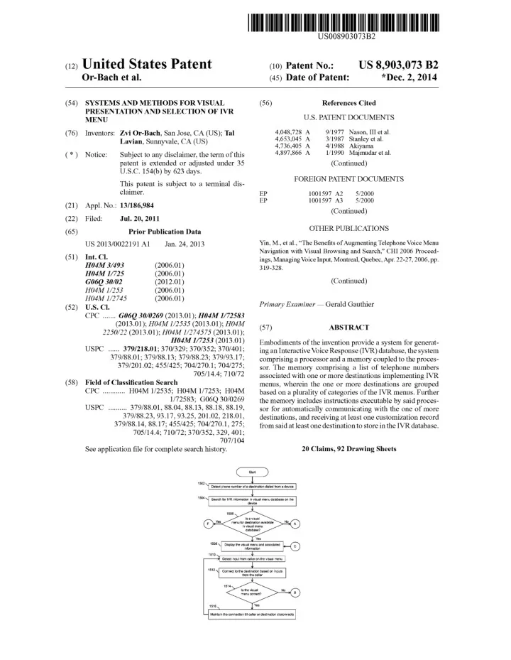
1502,~-"-~ 1504 ~-'-~ Isavisual F Yes menu for destination available In visual menu No A database?
slide-2
SLIDE 2

(56) References Cited

US 8,903,073 B2

Page 2

u.s. PATENT DOCUMENTS

6,169,734 Bl 6,212,547 Bl 6,228,921 Bl 6,229,694 Bl 6,230,197 Bl 6,259,444 Bl 6,263,064 Bl 6,321,198 Bl 6,335,678 Bl 6,366,650 Bl 6,373,817 Bl 6,400,807 Bl 6,405,033 Bl 6,408,301 Bl 6,427,063 Bl 6,445,694 Bl 6,449,595 Bl 6,456,706 Bl 6,459,776 Bl * 6,460,057 Bl 6,463,145 Bl 6,482,156 B2 6,505,146 Bl 6,510,411 Bl 6,529,500 Bl 6,560,320 Bl 6,594,484 Bl 6,603,840 B2 6,606,374 Bl 6,606,611 Bl 6,606,741 B2 6,636,835 B2 6,653,930 Bl 6,658,389 Bl 6,681,252 Bl 6,705,869 B2 6,714,519 B2 6,731,625 Bl 6,754,181 Bl 6,763,091 B2 6,788,770 Bl 6,791,583 B2 6,816,580 B2 6,820,037 B2 6,820,062 Bl 6,826,194 Bl 6,829,368 B2 6,836,762 B2 6,856,673 Bl 6,862,713 Bl 6,865,268 Bl 6,885,737 Bl 6,889,195 B2 6,920,205 B2 6,920,425 Bl 6,920,431 B2 6,937,705 Bl 6,990,455 B2 7,020,609 B2 7,027,571 Bl * 7,027,990 B2 * 7,036,128 Bl 7,039,589 B2 7,047,196 B2 7,065,188 Bl * 7,068,643 Bl 7,092,738 B2 7,100,118 Bl 7,130,391 B2 7,130,800 Bl 7,136,480 B2 7,139,591 B2 7,145,898 Bl 7,145,902 B2 7,146,321 B2 7,149,549 Bl 7,159,008 Bl 7,177,814 B2 7,180,889 Bl 5,006,987 A 5,007,429 A 5,027,400 A 5,086,385 A 5,144,548 A 5,265,014 A 5,294,229 A 5,335,276 A 5,416,831 A 5,417,575 A 5,422,809 A 5,465,213 A 5,465,401 A 5,475,399 A 5,499,330 A 5,519,809 A 5,533,102 A 5,550,746 A 5,572,581 A 5,576,951 A 5,585,858 A 5,586,235 A 5,588,044 A 5,592,538 A 5,606,361 A 5,633,909 A 5,633,916 A 5,657,221 A 5,689,648 A 5,708,422 A 5,724,412 A 5,737,393 A * 5,739,814 A 5,740,549 A 5,768,142 A 5,790,652 A 5,794,205 A 5,796,806 A 5,802,283 A 5,802,526 A * 5,807,336 A 5,819,225 A 5,822,404 A 5,822,405 A 5,838,682 A 5,838,775 A 5,867,816 A 5,873,068 A 5,885,083 A 5,885,245 A 5,890,123 A 5,892,813 A 5,907,793 A 5,912,952 A 5,913,195 A 5,920,477 A 5,937,040 A 5,940,488 A 5,948,040 A 5,956,034 A 5,982,875 A 5,987,103 A 6,009,398 A 6,014,428 A 6,020,915 A 6,049,779 A 6,055,513 A 6,062,863 A 6,088,429 A 6,088,712 A 6,091,805 A 6,091,956 A 6,104,790 A 6,144,848 A 6,148,065 A 411991 Harless 4/1991 Treatch et al. 6/1991 Baji et al. 211992 Launeyet al. 911992 Salandro 1111993 Haddock et al. 311994 Hartzell et al. 811994 Thompson et al. 511995 Chewning, III et al. 511995 McTaggart 611995 Griffin et al. 1111995 Ross 1111995 Thompson 1211995 Borsuk 311996 Lucas et al. 511996 Husseinyet al. 711996 Robinson et al. 811996 Jacobs 1111996 Sattar et al. 1111996 Lockwood 1211996 Harper et al. 1211996 Kauffman 1211996 Lofgren et al. 111997 Kosowsky et al. 211997 Davidsohn et al. 511997 Fitch 511997 Goldhagen et al. 811997 Warman et al. 1111997 Diaz et al. 111998 Blonder et al. 311998 Srinivasan 411998 Wolf .......................... 379/88.13 411998 Ohara et al. 411998 Reilly et al. 611998 Jacobs 8/1998 Gulleyet al. 811998 Walters et al. 811998 Birckbichler 911998 Gradyet al. 911998 Fawcett et al. ............. 379/88.13 911998 Russo et al. 1011998 Eastwood et al. 1011998 Cave 1011998 Astarabadi 1111998 Dekelbaum et al. 1111998 Montalbano 211999 Nussbaum 211999 Beaumont et al. 311999 Ferrell 311999 Lynch et al. 311999 Brown et al. 411999 Morin et al. 511999 Rearns 611999 Brendzel 611999 Weeren et al. 711999 Hofiberg et al. 811999 Wrede et al. 811999 DeGrazia et al. 911999 DeLorme et al. 911999 Sachs et al. 1111999 Lieben et al. 1111999 Martino 1211999 Mueller et al. 112000 Wolf 212000 Bruno et al. 4/2000 Berkson 4/2000 Katz et al. 5/2000 Kirksey et al. 7/2000 Garcia 7/2000 Huang et al. 7/2000 Watson 7/2000 Hollenberg 8/2000 Narayanaswami 1112000 Walsh et al. 1112000 Katz 112001 Wilson 4/2001 Ludwig et al. 5/2001 Kasemann et al. 5/2001 Kono 5/2001 Beck et al. 7/2001 Palmer et al. 7/2001 O'Neal et al. 1112001 Hank et al. 112002 Heutschi 4/2002 Rhie et al. 4/2002 Kung et al. 6/2002 Hewitt et al. 6/2002 Kennedy, III et al. 6/2002 Patton et al. 7/2002 Cook et al. 912002 Swartz 912002 Arslan et al. 912002 Blood et al. 1012002 Aktas et al. ................ 379/88.13 1012002 Butler et al. 1012002 O'Neal et al. 1112002 Iliff 112003 Blackmer 112003 Norton et al. 3/2003 Pandharipande 5/2003 Paleiov et al. 7/2003 Hitchings, Jr. 8/2003 Fellingham et al. 8/2003 Rokoff et al. 8/2003 Khan 8/2003 Kojima et al. 10/2003 Ragsdale-Elliott et al. 1112003 Bonomo et al. 12/2003 Alpdemir 112004 Schuster et al. 3/2004 Schwartz 3/2004 Luzzatti et al. 5/2004 Eastep et al. 6/2004 Elliott et al. 7/2004 Shimada 912004 Cook et al. 912004 Tang et al. 1112004 Timmins 1112004 Simon 1112004 Gupta et al. 1112004 Vered et al. 1212004 Meyer et al. 1212004 Speicher 212005 Banks et al. 3/2005 Kraft et al. 3/2005 Matthews et al. 4/2005 Gao et al. 5/2005 Strandberg 7/2005 Halm et al. 7/2005 Will et al. 7/2005 Showghi et al. 8/2005 Godfreyet al. 112006 Vozick et al. 3/2006 Thrift et al. 4/2006 Cook ......................... 379/88.17 4/2006 Sussman .................... 704/270.1 4/2006 Julia et al. 5/2006 Whitham 5/2006 Calderone et al. 6/2006 Mei et al. ................... 379/88.23 6/2006 Hammond 8/2006 Creamer et al. 8/2006 Klask 10/2006 Janakiraman et al. 1012006 Currey et al. 1112006 Mason 1112006 Callaghan et al. 1212006 Elliott 1212006 Schindler et al. 1212006 Cyr et al. 1212006 Ortiz et al. 112007 Wies et al. 212007 Gong et al. 212007 Kung et al.

slide-3
SLIDE 3

US 8,903,073 B2

Page 3 (56) References Cited

8,041,575 B2 * 1012011 Agarwal et al . ............ 704/270.1 8,054,952 Bl * 1112011 Or-Bach et al. ............ 379/88.18

U.S. PATENT DOCUMENTS

8,073,112 B2 * 1212011 Jaiswal et al. ............. 379/88.04 8,139,725 B2 * 3/2012 Cohen et al. ............... 379/88.14 7,180,985 B2 212007 Colson et al. 8,155,280 Bl * 4/2012 Or-Bach et al. ............ 379/88.13 7,181,401 B2 212007 Johnson et al. 8,160,215 B2 * 4/2012 Or-Bach et al. ............ 379/88.18 7,181,502 B2 212007 Incertis 8,223,931 Bl 7/2012 Lavian et al. 7,188,352 B2 3/2007 Nathan et al. 8,228,925 B2 * 7/2012 Cai et al. ....................... 370/401 7,203,517 B2 4/2007 Shimoda et al. 8,229,081 B2 * 7/2012 Agapi et al. ............... 379/88.04 7,206,745 B2 4/2007 Sarukkai et al. 8,265,234 B2 * 9/2012 Singh ......................... 379/88.04 7,206,809 B2 4/2007 Ludwig etal. 8,345,835 Bl * 112013 Or-Bach et al. ............ 379/88.23 7,209,124 B2 4/2007 Hunt et al. 8,406,388 B2 * 3/2013 Or-Bach et al. ............ 379/88.13 7,213,061 Bl 5/2007 Hite et al 8,467,506 B2 * 6/2013 Cohen et al. ............... 379/88.13 7,215,743 B2 5/2007 Creamer et al. 8,537,989 Bl * 912013 Lavian et al. .............. 379/93.17 7,216,348 Bl 5/2007 deCarmo 8,543,406 B2 * 912013 Wu et al. ....................... 704/275 7,225,409 B 1 5/2007 Schnarel et al. 8,548,131 Bl * 1012013 Lavian et al. .............. 379/88.18 7,225,455 B2 5/2007 Bennington et al. 8,548,135 Bl * 1012013 Lavian et al. .............. 379193.25 7,228,492 Bl 6/2007 Graham 8,553,859 Bl * 1012013 Lavian et al. .............. 379/93.17 7,231,636 Bl 6/2007 Evans 8,572,303 B2 * 1012013 Lavian et al. ................... 710172 7,231,656 Bl 6/2007 Nathan 8,594,280 Bl * 1112013 Or-Bach et al. ............ 379/88.01 7,240,006 Bl 7/2007 Brocious et al. 8,625,756 Bl * 112014 Lavian et al. .............. 379/93.17 7,240,289 B2 7/2007 Naughton et al. 8,634,521 B2 * 112014 Grigsby et al. ............ 379/88.18 7,246,063 B2 7/2007 James et al. 200210001371 Al 112002 Goldberg et al. 7,248,885 B2 7/2007 Benco et al. 200210055844 Al 5/2002 L'Esperance et al. 7,250,939 B2 7/2007 Lira 200210059138 Al 5/2002 Priest et al. 7,254,227 B2 8/2007 Mumicketal. 200210067816 Al * 6/2002 Bushnell .................. 3791201.02 7,265,861 Bl 912007 Ranalli et al. 200210147986 Al 1012002 Michael et al. 7,266,185 B2 912007 Trandaletal. 2003/0005126 Al 112003 Schwartz et al. 7,266,186 Bl 912007 Henderson 2003/0007625 Al 112003 Pines et al. 7,266,499 B2 912007 Surace et al. 2003/0033382 Al 212003 Bogolea et al. 7,272,222 B2 912007 Joseph et al. 2003/0039341 Al 212003 Burg et al. 7,272,497 B2 912007 Koshiji et al. 2003/0074198 Al 4/2003 Sussman 7,277,854 B2 1012007 Bennett et al. 2003/0112931 Al 6/2003 Brown etal. 7,280,097 B2 1012007 Chen et al. 2004/0034561 Al 212004 Smith 7,280,646 B2 1012007 Urban et al. 2004/0122941 Al 6/2004 Creamer et al. 7,280,651 B2 1012007 Anderson 2004/0196966 Al * 1012004 Bushnell .................... 379/88.19 7,286,990 Bl 1012007 Edmonds et al. 2004/0198316 Al 1012004 Johnson 7,289,608 B2 1012007 Kurnhyr 2004/0204116 Al 1012004 Ben

  • Efraim et al.

7,289,904 B2 1012007 Uyeki 2004/0217986 Al 1112004 Hambleton et al. 7,299,405 Bl 1112007 Lee et al. 2005/0004977 Al 112005 Roberts et al. 7,303,121 B2 1212007 Martinez 2005/0055310 Al 3/2005 Drewett et al. 7,319,477 B2 112008 Katz 2006/0165050 Al 7/2006 Erhart et al. 7,324,633 B2 112008 Gao et al. 2006/0187900 Al * 8/2006 Akbar ........................... 370/352 7,324,947 B2 112008 Jordan et al. 2006/0203977 Al 912006 Erhart et al. 7,328,239 Bl 212008 Berberian et al. 2006/0239422 Al 1012006 Rinaldo et al. 7,330,890 Bl 212008 Partovi et al. 2006/0259424 Al 1112006 Turcotte et al. 7,331,036 Bl 212008 Hambleton et al. 2006/0262921 Al 1112006 Eppel et al. 7,353,016 B2 4/2008 Roundtree et al. 2006/0277043 Al 1212006 Tomes et al. 7,366,287 B2 4/2008 Stroud et al. 2006/0285662 Al 1212006 Yin et al. 7,398,215 B2 7/2008 Mesbah et al. 2007/0026852 Al 212007 Logan et al. 7,406,413 B2 7/2008 Geppert et al. 2007/0032247 Al 212007 Shaffer et al. 7,412,533 Bl 8/2008 Johnson et al. 2007/0038513 Al 212007 Flax et al. 7,421,724 B2 912008 Klosterman et al. 2007/0094109 Al 4/2007 Perry 7,433,452 B2 1012008 Taylor et al. 2007/0123223 Al 5/2007 Letourneau et al. 7,440,898 Bl 1012008 Eberle et al. 2007/0223662 Al 912007 Jain et al. 7,450,112 B2 1112008 Shneidman 2007/0239537 Al 1012007 Protheroe et al. 7,460,652 B2 1212008 Chang 2007/0243887 Al 1012007 Bandhole et al. 7,466,803 B2 1212008 Burg et al. 2007/0298776 Al 1212007 Arlene 7,492,883 B2 212009 Kurnhyr 2008/0057943 Al * 3/2008 Shen et al. .................... 455/425 7,512,098 B2 * 3/2009 Jiang et al. .................... 370/329 2008/0066015 Al 3/2008 Blankenhorn 7,515,695 Bl 4/2009 Chan et al. 2008/0095330 Al 4/2008 Jin et al. 7,539,484 B2 5/2009 Roundtree 2008/0098353 Al 4/2008 Hambleton et al. 7,546,143 B2 6/2009 Nelson et al. 2008/0226042 Al 912008 Singh 7,584,249 B2 912009 Mumicketal. 2008/0250334 Al 1012008 Price 7,606,741 B2 1012009 King etal. 2008/0294448 Al * 1112008 Holtzclaw ......................... 705/1 7,646,858 B2 112010 Salafia et al. 200910041215 Al 212009 Schmitt et al. 7,693,720 B2 4/2010 Kennewick et al. 200910116414 Al 5/2009 Or et al. 7,716,055 Bl 512010 McIntosh et al. 200910136014 Al 5/2009 Bigue et al. 7,720,091 B2 512010 Faber et al. 200910154666 Al 6/2009 Rios et al. 7,729,490 B2 6/2010 Hemmetal. 200910202050 Al 8/2009 Berger et al. 7,757,173 B2 7/2010 Beaman 200910207980 Al 8/2009 Berger et al. 7,809,376 B2 10/2010 Letourneau et al. 200910207996 Al 8/2009 Berger et al. 7,813,485 B2 10/2010 Yinet al. 200910225788 Al 912009 Kephart et al. 7,843,899 B2 1112010 Burritt 200910228908 Al 912009 Margis et al. 7,864,944 B2 112011 Khouri et al. 200910245487 Al 1012009 Jockusch 7,908,381 B2 3/2011 Koch et al. 200910276441 Al 1112009 Malik 7,966,188 B2 6/2011 Ativanichayaphong et al. 200910276708 Al 1112009 Smith et al. 8,000,454 Bl * 8/2011 Or-Bach et al ............. 379/88.18 200910280863 Al 1112009 Shin et al. 8,023,624 B2 912011 Kargman et al. 200910285380 Al 1112009 Chen et al.

slide-4
SLIDE 4

(56) References Cited U.S. PATENT DOCUMENTS

201010007028 Al 112010 Fachmann et al. 201010021030 Al 112010 Collins et al. 201010049654 Al 212010 Pilo et al. 201010087175 Al 4/2010 Roundtree 201010100377 Al 4/2010 Madhavapeddietal. 201010166158 Al 7/2010 Costello et al. 201010172481 Al 7/2010 Canu et al. 201010185449 Al * 7/2010 Wu etal. 201010189250 Al 7/2010 Williams et al. 201110009096 Al 112011 Rotsztein et al. 201110014952 Al 112011 Minton 201110060683 Al 3/2011 Salmon Rock et al. 201110091021 Al 4/2011 Adkar et al. 201110099116 Al 4/2011 Gabel 201110276408 Al 1112011 Toole 201210035993 Al * 212012 Nangia 201210063574 Al * 3/2012 Or-Bach et al. 2013/0022191 Al * 112013 Or-Bach et al.

FOREIGN PATENT DOCUMENTS

EP 1120954 A2 8/2001 EP 1120954 A3 8/2001 EP 1225754 A2 7/2002 EP 1225754 A3 7/2002 EP 1351477 Al 10/2003 EP 1545101 A2 6/2005 EP 1545101 A3 6/2005 EP 774853 Bl 5/2006 EP 1874018 Al 112008 JP 8242307 A 9/1996 JP 2004274425 A 912004 WO WO-9819259 Al 5/1998 WO WO-9820409 A8 5/1998 WO WO-9840826 A3 9/1998 WO WO-9856158 A3 12/1998 WO WO 9848551 A3 4/1999 WO WO-0131497 Al 5/2001 WO WO-0157851 Al 8/2001 WO WO-0165871 Al 912001 WO WO-0217604 Al 212002 WO WO-2004049306 Al 6/2004 WO WO-2004064299 A2 7/2004 WO WO-2004064299 A3 7/2004 WO WO-2007012831 Al 212007 WO WO-2007081929 A2 7/2007 WO WO-2007081929 A3 7/2007 WO WO-2008086320 Al 7/2008 WO WO-2009006173 A2 112009 WO WO-2009006173 A3 112009 WO WO-2009100477 Al 8/2009

US 8,903,073 B2

Page 4

704/275 705/14.4 379188.23 3791218.01

OTHER PUBLICATIONS

Damhuis, M., et aI., "A Multimodal Consumer Information Server with IVR Menu," 2nd IEEE Workshop on Interactive Voice Technol-

  • gy for Telecommunications Applications (IVTTA94), Kyoto, Japan,
  • Sep. 25-27, 1994, pp. 73-76.

Trihandoyo, A., et aI., "A real-time speech recognition architecture for a multi-channel interactive voice response system," International Conference on Acoustics, Speech, and Signal Processing, vol. 4, 1995,pp.2687-2690. Shah, S.A.A., et aI., "Interactive Voice response with Pattern Recog- nition Based on Artificial Neural Network Approach," International Conference on Emerging Technologies, (ICET 2007), Nov. 12-13, 2007, pp. 249-252. Hattori, S., et al., "A multimedia intelligent message communication system for distributed coordination environments," Electronics & Communications in Japan, Part I-Communications, vol. 76, No.1,

  • pp. 11-23 (1993).

Kalva, H., et al., "Delivering Object-Based Audio-Visual Services," IEEE Transactions on Consumer Electronics, vol. 45, No.4, pp. 1108-1111, (1999). Schmandt, "Phoneshell: the telephone as computer terminal," Pro- ceedings offirstACM International Conference on Multimedia, Ana- heim, CA, US, pp. 373-381, (1993). Himberg, J., et aI., "Time Series Segmentation for Context Recogni- tion in Mobile Devices", IEEE, 203-210, (2001). Schmandt, et aI., "Phonetool: Integrating Telephones and Worksta- tions," IEEE Communication Society, Nov. 27-30, pp. 0970-0974, (1989). Basinger, R. G., et aI., "Calling Card Service-Overall Description and Operational Characteristics", The Bell System Technical Jour- nal, (1982). Cadiz et al. "Designing and Deploying an Information Awareness interface" CSCW'02, Nov. 2002, ACM, pp. 314-323. Corcoran et al. disclose "User interface technologies for home appli- ances and networks", IEEE Trans. Consumer Elect.; pp. 679-685, (1998). Friedrich, "Graphical-User-Interface Module Eases Integration," Wireless Systems Design, Oct. 2004, 3 pages. Steul, D., "Redefining the Call Center: Customer Service on the Internet", Alcatel telecommunications Review, Alcatel, Paris Cedex, FR, 6, (Mar. 2000). Balachandran, R., et aI., "Dialog System for Mixed Initiative One- Turn Address entry and Error Recovery," Proceedings of SIGDIAL 2009, the lOth Annual Meeting of the Special Interest Group in Discourse and Dialogue, pp. 152-155, Queen Mary University of London, Association of Computational Logistics, (2009).

*

cited by examiner

slide-5
SLIDE 5

u.s. Patent

  • Dec. 2, 2014

co .0

00 00 ...-- ...--

c c

.Q .Q

...... ......

co co

c c

...... ......

C/) C/) (]) (])
  • .
(])

(]) c (.) 0

.- ..c

>0.

(]) (])

0-

~ --

Sheet 1 of92

(.)

00 ...--

c

.Q

......

co

c

......

C/) (]) (])
  • o::::t

c

...--

..c 0.

:::J C/)

:>

co

N

...--

'-

(])

co

<D

()

...--

C

00 ...--

  • c

.Q

......

co

c

......

C/) (])

US 8,903,073 B2

(9

LL

slide-6
SLIDE 6

u.s. Patent

  • Dec. 2, 2014

Sheet 2 of92

US 8,903,073 B2

co .0

(.) C

00 00 00 00 ...-- ...-- ...-- ...--

c c c c

.Q .Q .Q .Q

...... ...... ...... ......

co co co co

c c c

  • • •

c

:;:::; :;:::; :;:::; :;:::; C/) C/) C/) C/) (]) (]) (]) (])

<D ...-- ...--

>. co

3:

z

(()

(])

I-

...... if)

T"""

co

(!)

a..

...--

(9

...--

LL

  • .

a..

(])

>

C

.0

~

(]) +

  • o::::t

'-

(.)

..c

.> ID

Q.

...--

3:

(]) ......

:::J

......

O:::J

C/)

.0

(])

Q.

:>

N

z

E

...--

()

  • N

...-- ...--

'-

(])

co

<D

()

...--

slide-7
SLIDE 7
slide-8
SLIDE 8

108a J Destination Board

1.r 202a

  • Maln-Menlimn m

_

m~t~m~

~ ~ m

nnmm n

r 222a

n:~

~ ~ ~ ~mnmn

m n

m! Number I

I

  • n

n

n.l_

I

i

I

n n

i

I

,--- - Press 2 for

~

204a 11 Pizza Orde ~ Press 3 206a Order Status

7\

]210a

r1 Press 1 for

208a.l I Veg Press 2 for Non-Veg Press 1 to tal k to the Executive

, C?<J ,

Press 1 for

t-I

Home 214a..ll Delivery Press 2 for I r 216a Take f1 Away

I

Pre,ss 0 for maIn menu 220a J 212a

V

218a

  • ~
  • ~

FIG.2A

~

7Jl

  • ~

~ ~

~ = ~

c

('D ~ N ~

N

  • ....
.j;o.

rFJ

=-

('D ('D

.....

.j;o.
  • .....

\0

N

d

rJl

QO

\c

=

w

  • =
  • ....l

W

=

N

slide-9
SLIDE 9

102b

Device

1----------------------------------------------------------------

I I L_

Board number

1

202b 206b

Pizza Order Order Status 3

208b 214b 204b .J I 2

Veg

1

Home Delivery

1

222b-y ------

Non-Veg

2

Take Away

2

210b

Talk to Executive

1

216b 212b 108a

Destination

110

  • FIG. 28

~

7Jl

  • ~

~ ~

~ = ~

c

("D ~ N ~

N

  • ....
.j;o.

rFJ

=-

("D ("D

.....

Ul

  • ....

\0

N

d

rJl

QO

\c

=

w

  • =
  • ....l

W

=

N

slide-10
SLIDE 10

102b .J I Device Board number 1 Pizza Order rder Statu 204c .J I r;$ 2

  • 3

210c

I

Talk to Veg Non-Veg Executive 208c ./ I #1

';#:2 , 1

Home Delivery 214c.J I Q 1 Take Away 216c

1:

2

/' : 2~-7-
  • --- -- -- ----- -- ---

108a Destination 110

I _

212c

I

116

FIG.2C

~

7Jl

  • ~

~ ~

~ = ~

c

('D ~ N ~

N

  • ....
.j;o.

rFJ

=-

('D ('D

.....

0\

  • ....

\0

N

d

rJl

QO

\c

=

w

  • =
  • ....l

W

=

N

slide-11
SLIDE 11

102b 204c 226 224 Device Welcome to our Pizza place. Please press 1 to check your order status

  • r press 2 to make a new order

Pizza Order rder Statu

~2

8

1 222 206c Please press 1 for vegetarion order or press 2 for non-vegetarian pizza order 208c \J Veg

#1

Non-Veg l! 210c

1K2

  • ~-"

222c

FIG.2D

~

7Jl

  • ~

~ ~

~ = ~

c

('D ~ N ~

N

  • ....
.j;o.

rFJ

=-

('D ('D

.....

  • ....l
  • .....

\0

N

d

rJl

QO

\c

=

w

  • =
  • ....l

W

=

N

slide-12
SLIDE 12

Device

(ComputerISmartphone)

)302

4

Radio ""

....:!!o.

Display

......

Interface

j304

Central Processing Unit

~

....:!!o.

Network Interface 324 ) 102a

,;

) 306 Memory

I

I n put/Output

I

~

Visuphone

.,.

interface 104 Visual Menu Database

~

308 Other Applications 310 i

FIG.3A

r-y~

V

312 y Gateway'

V

314

~.

Y""'

""

  • -'-

Network

......

,

V

316

112

V 3

~

Memory .--- Card 3

  • H Keyboard

I""

3~
  • .J Mouse

'I ~H

USB

l.f~

11

326

a

b

2

e

  • 7Jl
  • ~

~ ~

~ a

c

('D ~ N ~

N

....

.j;o.

rFJ

=-

('D ('D

.....

QO
  • ....

\0

N

d

rJl

QO

\c

=

w

  • =
  • ....l

W

=

N

slide-13
SLIDE 13

Device

(ComputerfSmartphone)

j302

I~

Display

.",

....

Radio Interface 304

f

324

Central Processing Unit

~ /"

....

Network

,

Interface Memory 102a VOIP Application 340 306

I

Visuphone

I

....

Input/Output 104

~

interface

(

Visual Menu Database 308 Other Applications 310

  • FIG. 38

f 312 y

Gateway'

f 314

~y-~

" Network

,

,.

112

f 316

3'

;--~

Memory V Card 3: LI- ~ Keyboard 3:

.....

USB

,

  • ~

Mouse I

11

  • 324

~

7Jl

  • ~

~ ~

~ = ~

c

("D ~ N ~

N

  • ....
.j;o.

rFJ

=-

("D ("D

.....

\0

  • ....

\0

N

d

rJl

QO

\c

=

w

  • =
  • ....l

W

=

N

slide-14
SLIDE 14

u.s. Patent

  • .

~

())

(]) c

.~

.§.

> ......

(]) ....
  • ~
(f)
  • N
  • .::t
  • en

00 I'--

I

<D

L!)
  • .::t
I C")

N

...--

  • Dec. 2, 2014

Sheet 10 of 92

00

  • .::t
  • ~-r_'_

"-----...

(.)

N

  • ...--

~

>. .0

  • :~

a~

0... co

......Q.

(.) E

:::J 0

"0(.)

e

Q.

3:

(])

z

US 8,903,073 B2

  • N
C")

rnJ[l]

GG

GEJ

GG GG GG

GG

  • .:::t

(9

LL

slide-15
SLIDE 15

512 J

Display

'I'

Device

(Computer) 'II

Display Interface

L..

502J I'

Central Processing Unit

...

504J I'

Memory

I I

Visuphone 104 Visual Menu Database

L

"'

506 J

308 Other Applications 510 110

LrE;

~Gateway

PSTN 112

"

4 'f526

,II

102b

~

Network V

514

Interface

V

516

518

  • -"-

Mouse

..

520 Input!

~

Keyboard

~

Output

~

522

.-

"'

interface

  • ;-

Speaker 7 Camera V

524

t:

  • -"-

Microphone V'"

....

~

FIG.5

23

~

7Jl

  • ~

~ ~

~ = ~

c

('D ~ N ~

N

  • ....
.j;o.

rFJ

=-

('D ('D

.....

.... ....

  • ....

\0

N

d

rJl

QO

\c

=

w

  • =
  • ....l

W

=

N

slide-16
SLIDE 16

u.s. Patent

N

  • <0
  • Dec. 2, 2014
  • en

co

l"-

I

<0 l!)

"""

I C'/')

N

..--

Sheet 12 of 92

N

..--

l!)

\

  • -------------------------------------------T--------------

'\

  • ..--

<0

"""

  • <0

co

  • <0
  • ~-

.0

N

  • ..--

N

..--

<0 <0

  • <0

"

>.

.0

  • :~
  • ~

D...ro

_0..

u E

::J 0

U

u

  • ..... N

0..>-

5:><

(])

z US 8,903,073 B2

CD

C)

LL

slide-17
SLIDE 17

u.s. Patent

"-

(]) (]) (.) C/)

">

3:

(])

e

(Q

  • Dec. 2, 2014

.0

N

  • ...--
(])

0'>

co

Q.

.0

(])

s

"

N I'--

Sheet 13 of 92

US 8,903,073 B2

......

(.)

I"--

(])

c

C

C)

() LL

"

<D I'--

"

  • o::::t

I'--

slide-18
SLIDE 18

u.s. Patent

  • Dec. 2, 2014

Sheet 14 of 92

US 8,903,073 B2

00

<D

'<j"

N

00 00 00 00

" " " "

C/)

c

.Q

......

co

(.)

Q. Q.

«

'-

(])

..c

......

E

(])

......

C/) (])

CO >.

C/)

'-

if)

'- co

0>

(])

3:

(9

> "E

c

.;:: ......

co

LL

co I '-

(])

Q.

(])

c ..c

Q.

:::J C/)

:>

~g

"

00

'<j"

...--

slide-19
SLIDE 19

~

7Jl VisuPhone

  • ~

r

902

~

Detection Module

~ ~ = ~

Search Module

r

904

c

('D

r

906

~

Display Module

N

~

N

....

r

90B

.j;o.

Connection Module

104

../1

rFJ

r

910

=-

('D

Voice Module

('D

.....

....

Ul

r

912

....

\0

Advertisement Module

N

Update Module

r

914

d

r

916

rJl

Customization Module

QO

\c

=

w

FIG.9

  • =
  • ....l

W

=

N

slide-20
SLIDE 20

Device Visual Menu Database 308 102 1004.11 Remote Repository 1002 1008 Remote Server computer Network Gateway 1006

  • FIG. 10

108a 1012a Audible IVR menu Repository Destination 1010

PSTN 1012n Audible IVR menu Repository Destination

~

7Jl

  • ~

~ ~

~ = ~

c

('D ~ N ~

N

  • ....
.j;o.

rFJ

=-

('D ('D

.....

....

0\

  • ....

\0

N

d

rJl

QO

\c

=

w

  • =
  • ....l

W

=

N

slide-21
SLIDE 21

u.s. Patent

co

00 ...--

c

.Q

......

co

c

......

C/) (])

co

00 ...-- ...... ......

(.) (])

N

c c

...--

()

...-- ...--

(]) (.)

'>

(])
  • Dec. 2, 2014

Sheet 17 of 92

.0

00 ...--

qeo ~ Ol pJ8MJO.::l '2:

(])

c

  • oo::::tl

"5.0

:::J"'--

C/)

:>

N

  • ...--
  • o::::t

...-- ...--

~

~

~

  • .....:
  • :f{J

'"'S Q

~

qj

~

~

C;;0

~

<D n,'

  • S

1J'

...-- ...--

~

§

(j

...-- ...--

c

.Q

......

co

c

......

C/) (])

US 8,903,073 B2

T""" T"""

(9

LL

slide-22
SLIDE 22

u.s. Patent

'<j"
  • N

...--

  • Dec. 2, 2014

<D

  • N

...--

N

...--

N

...-- <D ...--

N

...--

Sheet 18 of 92 E

(])

"0

  • :2:

>. co

3:

(])

......

co

(!) 00 ...--

N

...--

~ "-

3:

......

(])

z

US 8,903,073 B2

...--

(9

LL

slide-23
SLIDE 23

u.s. Patent

  • Dec. 2, 2014
  • ...--
('I')

...--

N

  • ('I')

...--

Sheet 19 of 92

c

.Q

N ......

...--

co

('I')

c

...--

......

(J) (])

<D

  • ('I')

...--

US 8,903,073 B2

slide-24
SLIDE 24

Add-On IE

I(!)

1410 1402 1404

FIG.14A

1414 1412

A~-onlD

1420

)~

1422 7

..!

  • --""'-)

FIG.14B

1428 1430

~

c::::J

1424 .L 1432 (---->

~;.~

.J )

c;;u j,

(

{"'"'"'

~i

Add-On

FIG.14C

~

7Jl

  • ~

~ ~

~ = ~

c

('D ~ N ~

N

  • ....
.j;o.

rFJ

=-

('D ('D

.....

N

  • ....

\0

N

d

rJl

QO

\c

=

w

  • =
  • ....l

W

=

N

slide-25
SLIDE 25

u.s. Patent

  • Dec. 2, 2014

Sheet 21 of 92

US 8,903,073 B2

1502 1504 Start Detect phone number of a destination dialed from a device Search for IVR information in visual menu database on the device Yes 1508 1510 1512 1516 Display the visual menu and associated information Detect input from caller on the visual menu Connect to the destination based on inputs from the caller

No

Maintain the connection till caller or destination disconnects

FIG.15A

slide-26
SLIDE 26

u.s. Patent

  • Dec. 2, 2014

Sheet 22 of 92 1518 Connect the device to a remote repository 1522 Update the visual menu database from 1526 remote repository Is the visual menu available in updated visual menu database? Update the remote repository Stop

  • FIG. 158

US 8,903,073 B2

slide-27
SLIDE 27

u.s. Patent

  • Dec. 2, 2014

Sheet 23 of 92 Any menu selection detected on the device? 1530 Provide the dialed number as a destination to remote repository Stop

FIG.15C

US 8,903,073 B2 No

slide-28
SLIDE 28

u.s. Patent

  • Dec. 2, 2014

Sheet 24 of 92 1558 Connect device to a remote repository Is there an updated version of the visual menu in the remote repository?

FIG.15D

US 8,903,073 B2

slide-29
SLIDE 29

1604 1610 Device Memory Database Construction System 1606 Records Database 1608 Processor 1612.11 Network Interface 1602 Gateway 1616

  • FIG. 16

Destination Destination

  • Destination

if

1620a 1620b 1620n

~

7Jl

  • ~

~ ~

~ = ~

c

('D ~ N ~

N

  • ....
.j;o.

rFJ

=-

('D ('D

.....

N

Ul

  • ....

\0

N

d

rJl

QO

\c

=

w

  • =
  • ....l

W

=

N

slide-30
SLIDE 30

u.s. Patent

  • Dec. 2, 2014

Sheet 26 of 92

US 8,903,073 B2

00

N

...-- I'-- I'-- I'-- ...-- ...-- ...--

" " "

E

(])

...... ......

C/)

c

>.

(])

if)

0'>

(])

«

c

«

:::J (])

.Q

c

"0

I"--

......

.Q

:::J T""" (.)

:2:

"0

:::J

......

'-

(.)

......

:::J C

:2:

(9

C/)

'- .Q

c

......

C/)

......

"0

LL c

co co

()

.~ (])

()

co

c

C/) (])

c 3:

co

C/)

.0 co

C/)

co '-

......

.0

(])

co co

a..

......

co

slide-31
SLIDE 31

Database Construction Agent

1722

Targets List Module

L

..

...

I

,

;:0

I

(J)

"0

IVR Tracking Module

(J) ;:::;:

1726 -'1

IVR Logic Module

I

  • ,

'< ()

1720 ~

::l

..L

1728

Tree storage Module

::l

,

...

(J) .....

,

(") r-t-
  • ·

1730

::l

Dialog Module

,.

...

~

,

Q.

1732 \...

c

Speech Recognition

(J)

Module

~ 1734 '1

Response Module

I

1738 1736

VOIP Connection Module I \..1724

,

\,

,

,

,

,

, ,

VOIP Application

, ,

...r 1740

,

Destination

,..,

....

, ,

, ,

....

, ,

,

, ,

,

,

~ _____________________________________________________ ______________ J
  • FIG. 178

..

Records

.....

Database

!

1608

~

7Jl

  • ~

~ ~

~ = ~

c

('D ~ N ~

N

  • ....
.j;o.

rFJ

=-

('D ('D

.....

N

  • ....l
  • ....

\0

N

d

rJl

QO

\c

=

w

  • =
  • ....l

W

=

N

slide-32
SLIDE 32

Database Construction Agent

1722 "-

Targets List Module ...

"-

,

I

:::0

CD

"0

IVR Tracking Module

(J) ;::::;:

1726 ~

I

IVR Logic Module

....,

'<

(")

1720

::J

1728

Tree storage Module

::J

....

...

CD "-

,.

(")

......

0"

1730

::J

Dialog Module ...

....

~

...

Q.

1732 \..

c

Speech Recognition

CD

Module

1734 ~

Response Module

I

~ 1738 1737

IVR Connection Module

I "-1724

I

,~

Destination

FIG.17C

1.£

...

Records

....

.,

Database

!

1608

~

7Jl

  • ~

~ ~

~ = ~

c

('D ~ N ~

N

  • ....
.j;o.

rFJ

=-

('D ('D

.....

N

QO
  • ....

\0

N

d

rJl

QO

\c

=

w

  • =
  • ....l

W

=

N

slide-33
SLIDE 33

u.s. Patent

1802 1804 1806

No

  • Dec. 2, 2014

Sheet 29 of 92 Start Connect to a destination Analyze a first level of the audible IVR menu Store the information regarding the audible IVR menu in a database 1810,-- Analyze the sub-menus 1812 Store the information regarding the sub-menus in the database Stop

  • FIG. 18

US 8,903,073 B2

Yes

slide-34
SLIDE 34

Category A

~

1904

Category B

~

1906

IVR

  • Categories

Category C

~

1908

Category D

4

1910

....

Dial Tone Selection

,.

Starting Questions

"-

and

,.

Dial Tone Selection Personal Information

.....

and

,

Dial Tone Selection Dial Tone Selection

.....

and/or

,

Natural Language Selection

  • FIG. 19

~

7Jl

  • ~

~ ~

~ = ~

c

('D ~ N ~

N

  • ....
.j;o.

rFJ

=-

('D ('D

.....

(.H
  • ....

\0

N

d

rJl

QO

\c

=

w

  • =
  • ....l

W

=

N

slide-35
SLIDE 35

u.s. Patent

  • Dec. 2, 2014

Sheet 31 of 92

US 8,903,073 B2 2002 ~,-

__

R_e_c_or_d_D_a_t_abr-a_s_e_c_o_n_te_n_t_~J

v

2004a J

Please enter invoice number

~

2006a J

Please enter the payment amount ~

2008a .-/

Please choose your payment card: Press 1 for VISA or 2 for MasterCard

!

2010a .-/

Please say or enter your Credit Card number

1

2012a .-/

Please enter your Credit Card expiry date

FIG.20A

slide-36
SLIDE 36

u.s. Patent

  • Dec. 2, 2014

Sheet 32 of 92

US 8,903,073 B2 Payment Form for ABC 2014 2004b

r------------------------------------------------- : Please enter invoice number: :

I I

/i I

I i

I I I ________________________________________________ J

2006b

~-I

: Please enter the payment amount :

I

) I

Ii

I I

: ________________________________________________ J

I

: Please choose your payment card:

2008b Jl t) VISA 0

MasterCard

I I ~- ______ I

2010b

~-I

: Please enter your Credit Card number :

) I

Ii

I I I ________________________________________________ J

2012b

:-Plea-se-entery-ourCredit-ca;:d-e~pirydate-:

I I

) I

Ii

I I I I I ________________________________________________ J

2016 '{

Submit J

FIG.2GB

slide-37
SLIDE 37

~

7Jl

  • Device

~

~ ~

2102a 2102c

~ =

f

~

Destination Destination Property 1 Property 1 C Property 2 Property 2

('D ~

Property 3 ~ Property 3

N

~
  • N
  • Property n

Property n

....

.j;o.

I I

f

K

  • 102
  • rFJ

=-

('D

2102b

/ \

  • ('D

.....

(.H (.H

Destination

/ \

  • ~

....

~ .. ~ .. I

I

.....

f2102n

\0

Property 1 ..

N

Property 1 / Property 2 Property 2 Property 3 Property 3

  • Property n

Property n

d

rJl

QO

\c

=

w

  • FIG. 21
  • =
  • ....l

W

=

N

slide-38
SLIDE 38

102a Device

I ---------------------------------------------------------------, I I I I I

Pizza Order I 2206./ I ~ 2 Board number

1

2208 Order status

  • 3

2212

I I

:2210

I I I

Veg

#1

Home Non-Veg

'ff2

7.

Take Delivery Away :2216- Q 1

>~

2

I

Talk to Executive , 1 2218 2214

I L __________

)'

__________________________________________________ _

2202

I

FIG.22

~

7Jl

  • ~

~ ~

~ = ~

C

('D ~ N ~

N

....

.j;o.

rFJ

=-

('D ('D

......

(.H .j;o.
  • ....

\0

N

d

rJl

QO

\c

=

w

  • =
  • ....l

W

=

N

slide-39
SLIDE 39

u.s. Patent

  • Dec. 2, 2014

Sheet 35 of 92

US 8,903,073 B2

2302 2304 2306 2308 Start Identify phone number of a destination dialed from a device Determine a location code associated with current location

  • f the device

Determine a business category associated with dialed phone number Search for destination phone numbers matching the business category of the dialed phone number stored on a database Yes 2312 Search for at least one destination phone number from the destination phone numbers based on location code

FIG.23A

slide-40
SLIDE 40

u.s. Patent

  • Dec. 2, 2014

Sheet 36 of 92

2328 2330 2332

Request updates from a server Receive updates from the server Store updates in the database

  • n the device
  • FIG. 238

US 8,903,073 B2

slide-41
SLIDE 41

u.s. Patent

2314 2316

  • Dec. 2, 2014

Sheet 37 of 92 Display the at least one destination phone number and associated properties 2318 Select a destination phone number, 2320 2322 Display a visual IVR menu of the selected destination Select an option from the visual IVR menu 2324 Connect to the selected option of the destination Stop

FIG.23C

No US 8,903,073 B2

2326 Display a visual IVR menu of the dialed destination phone number

slide-42
SLIDE 42

u.s. Patent

  • Dec. 2, 2014

Sheet 38 of 92

US 8,903,073 B2

Start 2402 \.. Identify a number of destination dialed by a caller of the device Search for an advertisement associated with the number in a database Yes Display the advertisement on the device Is a selection of advertisement by the caller detected? Stop

  • FIG. 24

No

slide-43
SLIDE 43

u.s. Patent

+-'

C (])

+-'

C

()

(]) (j)

co

.e

co

+-'

co

"'0

I- ()

(])

0:::

7

N

  • L!)

N

  • Dec. 2, 2014
  • co
'<j"
  • L!)

N

c

0)

I-

(]) +-' C (]) (]) (j)

co

(])

a..

Sheet 39 of 92

co

<D

  • L!)

N

"'0

l-

5

(j) (j)

co

Q. l-

(]) +-' C (]) (]) (j)

co

(])

a.. US 8,903,073 B2

«

L()

N

(9

LL

slide-44
SLIDE 44

u.s. Patent

N

~

t...

~

E

t...

L1.

c:

C)

...J

  • Dec. 2, 2014
  • ...--
L!)

N

  • '--"

>-

+-' +-'

C (])

"'0

c

0)

l-

(]) +-' C (]) (]) (j)

co

(])

a..

  • ~-

.0

'<j" L!)

N

"'0

l-

5

(j) (j)

co

Q.

I-

(]) +-' C (]) (]) (j)

co

(])

a..

  • ~-

.0

<D

L!)

N

Sheet 40 of 92

US 8,903,073 B2

+-'

E

(() ..c

L() ::J

N

(f)

C)

I

LL

00

L!)

N

slide-45
SLIDE 45

u.s. Patent

  • Dec. 2, 2014

Sheet 41 of 92

US 8,903,073 B2

Start

,~

2602

Dial a phone number of a destination

,~

2604 "-

Display a visual IVR menu corresponding to the dialed number on caller device

,

2606

Select an option from the displayed visual IVR menu

,~

2608 "'\...

Display a form indicating the information required by the IVR of the destination

,II

2610 "'\...

Fill the information in the displayed form

"

2612 "'\...

Establish a connection between the destination and the caller device

,~

Stop

  • FIG. 26
slide-46
SLIDE 46

102

/

2700

I
  • D

,-------

:

___________________ evice

I

r-~-

, I n~r I

/2704---------------------------"

2708" I ~ Veg 271

tJ1

Home 2716" I Delivery

I

t:t 1

1 2708 rder statu,

8

3

212

  • 2714
  • --,

Talk to Executive , 1 TakeAway 2718

1"

2 /\ ./"2720 Scheduling Mode

1 ______ ----------------------------------------------- ________________________ _
  • FIG. 27

lr

2702

1

~

7Jl

  • ~

~ ~

~ = ~

C

('D ~

~

N

....

.j;o.

rFJ

=-

('D ('D

......

.j;o.

N

  • ....

\0

N

d

rJl

QO

\c

=

w

  • =
  • ....l

W

=

N

slide-47
SLIDE 47

102 2810 2806

Personal Banking 2 Device Board number 1 Accounts 1 Deposits 2

2808

NRI Banking

3

Money Transfer 1

2812

  • 2824

Saving AlC 1 CreditA/C 2

2826

Investment 2 Talk to Executive 9

2828

Check I I Talk to Balance 1 executive 2

2818

'- 2820

Report lost card 1

2822

  • FIG. 28

2720

Scheduling Mode

V

2802 ~

7Jl

  • ~

~ ~

~ = ~

c

('D ~ N ~

N

  • ....
.j;o.

rFJ

=-

('D ('D

.....

.j;o. (.H
  • ....

\0

N

d

rJl

QO

\c

=

w

  • =
  • ....l

W

=

N

slide-48
SLIDE 48

Device 2904

¢

March 2011

L>

Sun

Mon

Tue Wed Thu

Fri

Sat

1

2 3 4 5 6 7 8 9

10

11

12 13 14 15 16 17 18 102 19 20

21

22 23 24 25 26 27 28 29 30

31

2906

/

i

Time

<

i

HH..(71 MM..(71 SS..(71 AM..(7

2900

  • FIG. 29

f 2902

~

7Jl

  • ~

~ ~

~ = ~

c

('D ~ N ~

N

  • ....
.j;o.

rFJ

=-

('D ('D

.....

.j;o. .j;o.
  • ....

\0

N

d

rJl

QO

\c

=

w

  • =
  • ....l

W

=

N

slide-49
SLIDE 49

u.s. Patent

  • Dec. 2, 2014

Sheet 45 of 92

US 8,903,073 B2 3002 3004 3006 3008 3010

Start Dial a phone number of a destination from a device Display a scheduling mode option and a visual Interactive Voice Response (IVR) menu associated with the dialed destination Switch the device to a scheduling mode Save a selection information including one or more options

  • f the visual IVR menu

Save a call schedule including a date and time information

FIG.30A

Wait for the call schedule's date and time

"

3014

slide-50
SLIDE 50

u.s. Patent

  • Dec. 2, 2014

Sheet 46 of 92

US 8,903,073 B2

A w

3016

Dial the phone number of the destination

,II

3018 \..

Request information from the destination based

  • n the selection information

,1/

3020

Receive the information at the device

,II

3022

Save the received information at the device

,II

3024

Display the received information at the device

,II

Stop

FIG.30B

slide-51
SLIDE 51

u.s. Patent

co

00

  • ...--
('I')

co

N

...--

('I')
  • Dec. 2, 2014
  • .
(])

c

(]) 0

u..c

.- a..

> (])

(])-

0:0

<D

  • ...--
('I')

:2:

  • '-
(])

co

()

(])

c ..c

Q.

:::J C/)

:>

co

  • o::::t

...--

('I')

Sheet 47 of 92

  • ...--

...--

('I')

~o

...--

('I')

US 8,903,073 B2

(9

LL

slide-52
SLIDE 52

u.s. Patent

.n

00 ...--

C"')

co

N

...--

C"')
  • Dec. 2, 2014

c

_Q ......

co

u

c

:::J

E

(])

u

E->

  • (])

00

"0

c

u

(])

(j)

  • (])
C

(])O

u..c

  • - a..

> (])

(])-

0:0

<D

  • ...--
C"')

~ '-

(])

co

  • (])

c ..c

Q.

:::J

en

:>

(])

c ..c

Q.

:::J

en

:>

.n

..;;t

...--

C"')

co

..;;t

...--

C"')

Sheet 48 of 92

  • ...--

...--

C"')

"'-0

...--

C"')

US 8,903,073 B2

slide-53
SLIDE 53

3106 Caller Network Device (Computer + VOIP) Visuphone 3104a 7

l'

3100 3114 Gateway PSTN

FIG.31C

3108b Second Communication Device Visuphone 3104b 7

~

7Jl

  • ~

~ ~

~ = ~

c

('D ~ N ~

N

  • ....
.j;o.

rFJ

=-

('D ('D

.....

.j;o.

\0

  • ....

\0

N

d

rJl

QO

\c

=

w

  • =
  • ....l

W

=

N

slide-54
SLIDE 54

Caller

3106

Network Device (Smartphone) Visuphone

3104a7 3114

J( )J Gateway

PSTN

FIG.310

3108b

Second Communication Device

\

3100

Visuphone

3104b7

~

7Jl

  • ~

~ ~

~ = ~

c

('D ~ N ~

N

  • ....
.j;o.

rFJ

=-

('D ('D

.....

Ul

  • ....

\0

N

d

rJl

QO

\c

=

w

  • =
  • ....l

W

=

N

slide-55
SLIDE 55

u.s. Patent

  • Dec. 2, 2014

Sheet 51 of 92

US 8,903,073 B2

  • --,

c

I.Q

I

......

IE N

I "- .0

(V)

IQN

Ico

C) I"-N

1"0 ('I')

ds

LL

1(.) lID if) N N

('I')
slide-56
SLIDE 56

Packet Version Traffic Class 3302 3304 Payload Length Next Header 3308 3310 Source Address 3314 Destination Address 3316 3202a

  • FIG. 33

Flow Label 3306 Hop Limit 3312

~

7Jl

  • ~

~ ~

~ = ~

c

('D ~ N ~

N

  • ....
.j;o.

rFJ

=-

('D ('D

.....

Ul

N

  • ....

\0

N

d

rJl

QO

\c

=

w

  • =
  • ....l

W

=

N

slide-57
SLIDE 57

u.s. Patent

3402

  • Dec. 2, 2014

Sheet 53 of 92

US 8,903,073 B2

Start Search, at a first communication device, for a data network Yes

No

a first section of a packet to the second communication device as Dual-Tone Multi- frequency signals 3408 Send a first section of the packet comprising first information to the second communication device Is Visuphone available at second communication device?

FIG.34A

slide-58
SLIDE 58

u.s. Patent

3412

  • Dec. 2, 2014

Sheet 54 of 92 Receive an acknowledgement message based

  • n the first section from the second

communication device

US 8,903,073 B2

Send a second section of the packet comprising 3414 second information based on the acknowledgement message to the second communication device Stop

  • FIG. 348
slide-59
SLIDE 59

3508a

First party device

3508b

First party device

3508c 3508n

First party device

  • First party

device PSTN

/

3500 3502a

Device (Mobile Phone) Visuphone

3504 7

FIG.35A

3506

Caller

~

7Jl

  • ~

~ ~

~ = ~

c

('D ~ N ~

N

  • ....
.j;o.

rFJ

=-

('D ('D

.....

Ul Ul

  • ....

\0

N

d

rJl

QO

\c

=

w

  • =
  • ....l

W

=

N

slide-60
SLIDE 60

3508a

First party device

3508b

First party device

3508c 3508n

First party device

  • First party

device

3512

Gateway 1('

')\

Network PSTN

l'

3502b

\

Device (Computer+VOIP)

l

  • Visu-ph-on-e -
  • I

35047 3500

  • FIG. 358

3506

Caller

~

7Jl

  • ~

~ ~

~ = ~

c

('D ~ N ~

N

  • ....
.j;o.

rFJ

=-

('D ('D

.....

Ul

0\

  • ....

\0

N

d

rJl

QO

\c

=

w

  • =
  • ....l

W

=

N

slide-61
SLIDE 61

~

7Jl

  • 3508a

r 3512

I

"\

~

~ ~

~

First party Gateway 1<

)l

Network

1.1

=

~

device 3508b

'\. \

#..../

C

('D ~

First party I~

~

1

N

3502c

~

N

device

\.,.

....

,.3506

.j;o.

Device 3508c

(" ~

I

(Smartphone) PSTN

~I

rFJ

II

<

Caller

=-

First party

I~

\

Y

('D

Visuphone

('D

.....

device

Ul

3504./

  • ---.l

....

  • /

f>--/

""

\0

N

  • 3508n • /

First party Cellular device

J

NetNOrky

d

rJl

3500

QO

\c

=

w

  • =

FIG.35C

  • -...l

w

=

N

slide-62
SLIDE 62

3508a

First party device

3508b

First party device

3508c 3508n

First party device

  • First party

device PSTN

3602

Third party device Device (Mobile Phone)

3502a

[

V~u~h~n;

  • -I

35047

l'

3500

  • FIG. 36

3506

Caller

~

7Jl

  • ~

~ ~

~ = ~

c

('D ~ N ~

N

  • ....
.j;o.

rFJ

=-

('D ('D

.....

Ul

QO
  • ....

\0

N

d

rJl

QO

\c

=

w

  • =
  • ....l

W

=

N

slide-63
SLIDE 63

3502 3710

________________________

~yice

number

1

Veg

t/1

Board 3704

1 :

,

, , ,

3712 Non-Veg

'$2

7.

3708 rder Statu

e 3

3714 Talk to Executive , 1

I 3720a

Communication Option

i

,

:;-370

13720b:

i '

Communication Option

  • ,

, , , ,

,

·

:

,

,

  • I 3720ni

Communication Option Home Take Away I r 3718 Del ivery

~

2

..I

L ___________

~

__ ~ _________

'~'~ _____________________________________________________

,

3716

  • FIG. 37

~

7Jl

  • ~

~ ~

~ = ~

c

('D ~ N ~

N

  • ....
.j;o.

rFJ

=-

('D ('D

......

Ul \0

  • ....

\0

N

d

rJl

QO

\c

=

w

  • =
  • ....l

W

=

N

slide-64
SLIDE 64

3502/

1

3806

Personal Banking 2 Device

Bo-ar-~-[(-38-04-.(-3~-02

number

  • 1

3808

NRI Banking

3

3826 ..L3720a

Communication Option Accounts

38101

1

Deposits 2 Money Transfer 1 Investment 2

f 3720b

Communication Option

7<

Saving ~C

II Credit~C

Check Talk to Balance 1

3818 3820 3812

  • 3824

Report lost card 1

3822

Talk to Executive 9

3828

  • f3720n

Communication Option

1 ____________________________________________________________________________________________ _
  • FIG. 38

~

7Jl

  • ~

~ ~

~ = ~

c

('D ~ N ~

N

  • ....
.j;o.

rFJ

=-

('D ('D

.....

0\

  • ....

\0

N

d

rJl

QO

\c

=

w

  • =
  • ....l

W

=

N

slide-65
SLIDE 65

u.s. Patent

<0

co

  • L(')

C'?

>-

t (])

<0 (.)

D.. .-

>

....... (]) .~

l..L

  • Dec. 2, 2014

to

  • 0')

C'?

Sheet 61 of 92

E

(])

"0

  • ~

_-.N

  • 0')

C'?

US 8,903,073 B2

slide-66
SLIDE 66

u.s. Patent

  • Dec. 2, 2014

Sheet 62 of 92

US 8,903,073 B2

Start 4002 Receive, at the device, a call from a phone number of a first party device 4004 Compare the phone number of the first party 4006 4008 4010 4012 device with the phone numbers stored in the device Display the visual IVR menu Display one or more communication options Select a communication option Establish a communication session based on the selection Stop

  • FIG. 40
slide-67
SLIDE 67

u.s. Patent

co

<D

  • ...--
'<j"

co(]) E (.)

(])O_

...... >

>< (])

LlJO

  • Dec. 2, 2014

co

E ~

(])O_

...... >

>< (])

LlJO

(])

.0 co

t

  • a..

Sheet 63 of 92

(.)

<D

  • ...--
'<j"

co

E ~

  • (])O_

...... >

>< (])

LlJO

N

  • ...--
'<j" C

<D

  • ...--
'<j"

co

E ~

(])O_

...... >

>< (])

LlJO

US 8,903,073 B2

slide-68
SLIDE 68

u.s. Patent

<D

  • N
'<j"
  • Dec. 2, 2014

N

  • N
'<j"

Sheet 64 of 92

  • 111.
111111 •
  • 111111
  • ..... .

co

N

  • ...--
'<j"

US 8,903,073 B2

slide-69
SLIDE 69

u.s. Patent

  • Dec. 2, 2014

v

0..

  • ......

0..

co

.....J

Sheet 65 of 92

US 8,903,073 B2

slide-70
SLIDE 70

u.s. Patent

  • Dec. 2, 2014

Sheet 66 of 92

co

N

  • ...--
'<j"

US 8,903,073 B2

slide-71
SLIDE 71

u.s. Patent

  • Dec. 2, 2014
,~
  • L!)
'<j"

co

N

  • ...--
'<j"

Sheet 67 of 92

US 8,903,073 B2

slide-72
SLIDE 72

u.s. Patent

  • Dec. 2, 2014

Sheet 68 of 92

US 8,903,073 B2

(0

  • .:::t

C)

"

LL

(])

E

co

"- LL

(])

"-

:::J

......

(.)

a..

\

N <D

'<j"
slide-73
SLIDE 73

u.s. Patent

  • Dec. 2, 2014

D~I\

I~

"

C (]) (])

"-

(.) C/)

if)

a..

(!)

co

N

  • ...--
'<j"

Sheet 69 of 92

US 8,903,073 B2

slide-74
SLIDE 74

u.s. Patent

>. co

0..

"~

"""

  • co

"""

  • Dec. 2, 2014

Sheet 70 of 92

D:

L-
  • u
(l)

"0'

L-

a..

N

  • co

"""

co

N

..--

"""

US 8,903,073 B2

00

""'"

(9

LL

slide-75
SLIDE 75

u.s. Patent

  • Dec. 2, 2014

Sheet 71 of 92

N

  • en
'<j"

c

(])

~

(.) C/)

>. co

0..

C/)

"0

(])

e>

co

.....J

N

  • .0
'<j"
  • en
'<j"
  • ~-

"-

(])

"E

ON

co

N .!:::!

a..

0'>

~ eN

  • z
1 ______ ---------------------------------------

US 8,903,073 B2

slide-76
SLIDE 76

5004 4102

Portable Device

5002

Display Processor Connection Manager

5008 5006

Memory Operating System

1010 5020

  • FIG. 50

Radio Interface Network Interface

5014 5018

~

7Jl

  • ~

~ ~

~ = ~

c

('D ~ N ~

N

  • ....
.j;o.

rFJ

=-

('D ('D

.....

  • ....l

N

  • ....

\0

N

d

rJl

QO

\c

=

w

  • =
  • ....l

W

=

N

slide-77
SLIDE 77

5004 4102

Portable Device

5002

Display Processor Connection Manager

5008 5106

Memory Operating System

5010 5020

  • FIG. 51

Radio Interface

5012 5014

Network Interface

~

7Jl

  • ~

~ ~

~ = ~

c

('D ~ N ~

N

  • ....
.j;o.

rFJ

=-

('D ('D

.....

  • ....l
(.H
  • ....

\0

N

d

rJl

QO

\c

=

w

  • =
  • ....l

W

=

N

slide-78
SLIDE 78

u.s. Patent

co

<D

  • N
U')

co

E ~

(])"- ...... > >< (])

LlJO

  • Dec. 2, 2014

Sheet 74 of 92

.0

<D

  • N
U')

co

E ~

(])"- ...... > >< (])

LlJO

(]) (.)

">

(]) (])

.0 co

......

'-

a..

(])

c

(.)

<D

  • N
U')

co

E ~

(])"- ...... > >< (])

LlJO

  • 001

..co

Q.N

:::JU')

C/)

:>

N N

U') (]) '-"~
  • o::::t

(]) >

C/)(])

N

::JO

U')
  • C

<D

  • N
U')

co

E ~

(])"- ...... > >< (])

LlJO

~8

N

U')

US 8,903,073 B2

N

L()

(9

LL

slide-79
SLIDE 79

u.s. Patent

co

<D

  • N
U') '<j"
  • N

'-~

U')

(])._

C/) >

:J~

  • Dec. 2, 2014

.0

<D

  • N
U')

N N

U') (]) (.)

.>

(]) (])

.0 co

......

'-

a..

(])

c

Sheet 75 of 92

(.)

<D

  • N
U')
  • 001

..co

Q.N

:::JU')

C/)

:>

C

<D

  • N
U')

US 8,903,073 B2

("') L()

(9

LL

slide-80
SLIDE 80

u.s. Patent

<D

  • N
  • o::::t

N

  • N
  • o::::t
  • Dec. 2, 2014
(]) (])

.0 (.) co .-

...... > '-

(])

00

a..

  • 11
  • I!! ,. ••
  • :IIi .II!
  • .

,. ..

  • .

"'".

  • o::::t
  • N
  • o::::t

Sheet 76 of 92

US 8,903,073 B2

0000

~-~

DODD D~

N

  • N
L!)

N

  • o::::t
L!)
slide-81
SLIDE 81

u.s. Patent

>.

co

0..

"~ o
  • o:::t"
  • L{)
L{)
  • Dec. 2, 2014

N

  • N
L{)

Sheet 77 of 92

US 8,903,073 B2

(]) (])

.0 U

co ":;: t (])

00

a...

0000

IE-.;~

0 0 0 0

N

  • L{)
L{)

DODD

N

  • o:::t"
L{)

L() L()

t9

LL

slide-82
SLIDE 82

u.s. Patent

  • Dec. 2, 2014

Sheet 78 of 92

(]) (])

.0 (.) co "::;:

t (])

00

a..

0000

~-~

DODD DODD

US 8,903,073 B2

(9

LL

slide-83
SLIDE 83

u.s. Patent

  • Dec. 2, 2014

Sheet 79 of 92

(]) (])

.0 (.) co .-

...... > '-

(])

0000

14'----+1 0 0 0 0

00

a..

N

  • N
L!)

DODD

N

  • o::::t
L!)

US 8,903,073 B2

slide-84
SLIDE 84

u.s. Patent

  • Dec. 2, 2014

Sheet 80 of 92

.0 (.)

ro·-

  • ~

0 0 0 0

<D<D

00000

...... >.....

,

~t3

r-

DODD",

"

Q.

  • ......

Q.

ro

.....J

"

N

  • ("I")
  • o::::t

N

  • N
L!)

/'

N

  • o::::t
L!)

US 8,903,073 B2

co

L()

(9

LL

slide-85
SLIDE 85

u.s. Patent

  • Dec. 2, 2014
(]) (])

.0 (.) co .-

...... > '-

(])

00

a..

(])

E

co '-

LL

(])

'-

:::J

......

(.)

a..

N

  • <D
  • o::::t

N N

L!)

Sheet 81 of 92

US 8,903,073 B2

(j)

L()

C)

LL

slide-86
SLIDE 86

u.s. Patent

  • Dec. 2, 2014
(]) (])

.0 (.) co "::;:

,

t

(])

.....

00

a..

'\

I~

N N

L!)

"

c

(]) (])

'-

(.) C/)

if)

a..

(!)

Sheet 82 of 92

0000

...

DODD

,

r--

DODD ~

N

  • o::::t
L!)

US 8,903,073 B2

slide-87
SLIDE 87

u.s. Patent

  • Dec. 2, 2014

Sheet 83 of 92

c

(]) (])

'-

(.)

if)

>. co

Q. N

C/)

...--

(])

<D

'"

0>

'- co

.....J

co

'<j"

...-- <D

N

(]) (])

[g]~

N

L!)

.0 (.) co .-

...... > '-

(])

00

a..

  • ~-

'- "0 (])

'-.0

~E"'- (Q

:::J C

'-

(])

"E

ON

co

N

.~ a..

0>

~ eN

  • z
1 ______ ---------------------------------------

US 8,903,073 B2

<D ...-- <D

slide-88
SLIDE 88

u.s. Patent

  • Dec. 2, 2014

~ (

  • (])
(.)

">

(]) (])

.0 co

"-

t

(])

0>

a..

co c

"-

co

~

<01

C/) C/)

cO

(])

2~

(.)

e

(.) (])

a..

c

C ()

Sheet 84 of 92

N

~

...-- "-

N <0

3:

......

(])

Z II'

,~ ~(]) "- (.)
  • co

3:'t:

"-~

...... (]) (]) ......

ZC

N <0

"

'<j"

...--

N <0

>.

"-

'<j"

E

N

(])

<0

~

~

\...,

N N <0

"

N

  • N
L!)

~

E

(])

......

C/)

>. 0>0

wool

:§~ co

"-

(])

Q.

US 8,903,073 B2

  • N

(0

(9

LL

slide-89
SLIDE 89

u.s. Patent

  • Dec. 2, 2014

Sheet 85 of 92 Start 6302 Search, at a portable device, for an external 6306 6308 device

No

Connect to the detected external device Display contents of display of the portable device on a screen of the external device Stop

  • FIG. 63

US 8,903,073 B2

slide-90
SLIDE 90

u.s. Patent

  • Dec. 2, 2014

Sheet 86 of 92

US 8,903,073 B2

Start 6402 Search, at a portable device, for a user device

No

6406 Establish a connection between the portable device and the detected user device 6408 Search, at the portable device, for an external device

No

FIG.64A

slide-91
SLIDE 91

u.s. Patent

  • Dec. 2, 2014

Sheet 87 of 92

US 8,903,073 B2

A

"

6412"'\.. Establish a connection between the portable device and the detected external device 6414 \.. Display contents of display of the user device

  • n a screen of the external device

Stop

  • FIG. 648
slide-92
SLIDE 92

102 Device

  • 6510

6571 Veg

t/1

Board Number 1 6512

I V- 6502 I I

6508:

r-~/~ I I I I

rder Statu

e 3

I I I I I I I

6514: Talk to Executive , 1

I I I I I I I I

Home Take Away r 6518 Del ivery

~

2

..I

Q

1

/'!

___________ _

  • FIG.65

J 6520a

Contact Option

J 6520b

Contact Option

  • f 6520n

Contact Option

~

7Jl

  • ~

~ ~

~ = ~

c

('D ~ N ~

N

  • ....
.j;o.

rFJ

=-

('D ('D

.....

QO QO
  • ....

\0

N

d

rJl

QO

\c

=

w

  • =
  • ....l

W

=

N

slide-93
SLIDE 93

u.s. Patent

  • Dec. 2, 2014

N

  • <D

<D

Sheet 89 of 92

US 8,903,073 B2

  • ~-

00

<D <D

"

:::J

......

roC'?

...... if)

~.

'--

>-''--

(])

(])

'--

(])

(.)

E(]).o .>

  • .;::: E...--
(])

I

(])

:::J

02

'--

(])

"EN

~ a..

"

<D <D <D N

  • ...--

N ...-- <D <D

'<j"

...-- <D <D

(])
  • .;:::

............

:::J"'-- ~

(.)

~(]) til_

0>

(0 ~N (0

~

(9

LL

...-- 0>

~

...-- <D <D

slide-94
SLIDE 94

102 Device

  • Booking

2 Enter Booking Information 1 XYZ Airlines If 6704 Board Number 1 Status Inquiry

3

Other Inquiry 4 6710 6716 Talk to Executive 2 Enter Airline Information 1 Talk to Executive 2

V 6702

6720a XYZ Domestic Airline Contact Option 6720b XYZ International Airline Contact Option

L ____________________________________________________________
  • FIG.57

~

7Jl

  • ~

~ ~

~ = ~

C

('D ~ N ~

N

....

.j;o.

rFJ

=-

('D ('D

.....

\0

....

\0

N

d

rJl

QO

\c

=

w

  • =
  • ....l

W

=

N

slide-95
SLIDE 95

102

Booking

2

Enter Bookingl Information 1 Device

6804

XYZ Domestic Airlines Number 1 Status Inquiry

3

6810

Other Inquiry

4

6816 6818

Talk to Executive

2

Enter Airline Information 1 Talk to Executive

2

Lf 6802

______________________________________________________ ---------------- ______ 1

FIG.68

~

7Jl

  • ~

~ ~

~ = ~

c

('D ~ N ~

N

  • ....
.j;o.

rFJ

=-

('D ('D

.....

\0

....

  • ....

\0

N

d

rJl

QO

\c

=

w

  • =
  • ....l

W

=

N

slide-96
SLIDE 96

u.s. Patent

  • Dec. 2, 2014

Sheet 92 of 92

US 8,903,073 B2

Start

"

6902 '-.

Dial, at the device, a phone number of a destination W

6904 '-... Display the visual IVR menu associated with the

dialed phone number

,~

6906

Display one or more contact options

\V

6908

Select at least one contact option v

6910

  • Change the display of the visual IVR menu

based on the selection of the contact option

,~

Stop

  • FIG. 69
slide-97
SLIDE 97

US 8,903,073 B2 1

SYSTEMS AND METHODS FOR VISUAL PRESENTATION AND SELECTION OF IVR MENU FIELD OF THE INVENTION The invention relates to Interactive Voice Response (IVR) system and more specifically the invention relates to visual selection of IVR option from a caller device. BACKGROUND OF THE INVENTION Interactive Voice Response (IVR) technology is generally used to detect voice and key inputs from a caller. The advent

  • f Interactive Voice Response (IVR) systems has reduced
  • perating costs for many types of businesses for providing
  • services. Generally, the IVR systems allow a user to interact

with an audio or visual response system. The IVR systems can provide prompts to a user and receive touch tone and/or spoken responses on the prompts from the user. Through such IVR dialogue the system collects sufficient information about the user to direct the call to the most appropriate resource, information processing system or the like.

2

Some prior art try to address this problem by providing visual form of IVR. These prior arts display the IVR menu graphically on a caller device. U.S. Pat. No. 7,215,743 assigned to International Business Machines Corporation and a published U.S. patent application Ser. No. 111957,605, filed

  • Dec. 17, 2007 and assigned to Motorola Inc., provides the

IVR menu of the destination in a visual form to the caller. The caller can select the options from the IVR menu without listening to the complete audio IVR menu. However, the IVR

10 menu displayed on

the caller device is stored on an IVR server at the destination end. As a result, the visual IVR menu is specific to the destination and only the IVR of the destination dialed is displayed. These techniques therefore, require each destination to set-up hardware, software and other facilities to

15 be deployed for providing visual IVR servers.

A U.S. Pat. No. 7,460,652, assigned to AT&T Intellectual Property I, L.P., discloses techniques for call routing and communication with a call originator. The call may be received at an automated call handling system. Thereafter, the

20 call is evaluated based on a set of

business rules and routed to an interactive voice response unit based on the evaluation. Further, the interactive voice response unit automatically schedules and sends an email to the originator of the call. Generally, when the caller calls a destination, such as a 25 bank, an automated audio IVR menu is played. The audio IVR menu can contain instructions to provide instant services such as account balance inquiry when the destination is a

  • bank. Further, audio menu can provide options for the caller

However, the scheduling of the email is performed after establishing a communication with the automated call han- dling system. Moreover, the scheduling is performed at the automated call handling system. Another existing technique as disclosed in U.S. Pat. No. 6,560,320 assigned to International Business Machines Cor- poration enables an operator of the IVR to send customized signals to the caller for generating and displaying graphical to connect to a desired end inside the destination. For 30 example, the menu may direct the caller to press various keys

  • n a telephone to connect to a particular department or agent.

The audio IVR menu is designed specific to a destination. Therefore, each destination or organization may have differ- ent audio IVR menus. Further, the IVR menu in an organiza- tion can be based on the type of departments, type of services, customer care executives or agents and so forth. For example, an IVR menu of a bank may include options related to the account details of the caller, while an IVR menu of a pizzeria may contain options to order or select a pizza. Typically, the caller calling the destination may have to listen and follow instructions on the menu to get a desired response or a function performed. Therefore, the process can be time consuming. Moreover, in case the caller provides an incorrect input, the complete process may have to be

  • repeated. Furthermore, the IVR menu for an organization

may be updated or changed regularly. For example, extension numbers inside an organization may be changed and corre- spondingly, the extension numbers associated with the IVR menu may be updated. As a result, a frequent caller may not be able to reach a desired end by remembering a combination

  • f numbers. Furthermore, the dialed destination may not

include the information desired by the user. In such a case, the user may have to call the destination again for retrieving the desired information. Therefore, the user may become frus- trated with the IVR systems. Usually, the IVR menus are same for all the users. There- fore, the customer has to listen them carefully to select the appropriate option. The user may have to wait for long time for receiving information while interacting with the IVR sys-

  • tems. Moreover, sometimes the requested information might

not be available at the time when the user calls the destination. Therefore, the user may have to either wait for long time or call again later. For example, the user may desire to talk to a customer care executive of the destination, who is busy at the time of the call. Therefore, the call of the user may be put on hold or he may be asked to call later. elements on the device of the caller. Thereafter, the caller can respond by selecting options through touch-screen interface

  • f

the device. Dual Tone Multi frequency (DTMF) signals of

35 the IVR. However, this technique requires a specifically con-

figured device to interpret the codes sent as Dual Tone Multi frequency (DTMF) signals for generating the graphics. More-

  • ver, an operator is required to present the graphics to the
  • caller. Furthermore, specialized software and hardware are
40 required at the operator to design and generate DTMF codes.

Therefore, the technique faces various practical limitations. Generally, the IVR menus of the organizations are in form

  • f

audible menu. Moreover, there are a large number of

  • rga-

nizations that use IVR menus. Therefore, converting the

45 audible menus to visual IVR menus can be time consuming.

An existing technique, as disclosed in U.S. Pat. No. 6,920,425 assigned to Nortel Networks Limited, discloses an automated script to convert the audible menus scripts to visual IVR menu

  • scripts. However, the audible menus scripts must be available
50 in a particular format to enable the conversion. Furthermore,

the audio menu scripts must be available or downloadable for the program to function. As a result, only the audio menus scripts that are available can be converted to visual IVR menu

  • scripts. Furthermore, the device of

the caller must be designed

55 or progranlilled to understand the visual IVR menu scripts.

Various organizations encourage the customers to call them for information on their products or services, or for helping existing customers. Generally, a contact number is provided by the organizations on their website as a button.

60 Therefore, when the customer presses the button a form is
  • displayed. The customer then enters his contact number

where an executive from the organization may call. However, this may be time consuming for the customer. Moreover, the customer may be not being able to talk to another executive

65 during the call in case the on-line executive is not able to

satisfy the customer. U.S. patent application Ser. No. 12/049, 021, filed Mar. 14,2008 and assigned to Harprit Singh, pro-

slide-98
SLIDE 98

US 8,903,073 B2 3

vides methods and systems for displaying an IVR menu, when the caller clicks a link on a webpage provided by the

  • rganization. However, the customer is still required to

request the webpage with embedded infonnation from a server of the organization. Moreover, the methods and sys- tems are limited to the organizations that provide the required webpage to the customers. Other technologies include u.s. patent application Ser. No. 11/877,952 filed Oct. 24, 2007 and assigned to International Business Machine Corporation.

4

Visuphone may provide pre-recorded or computer synthe- sized audio responses on behalf of the caller to the destina- tion. An aspect of the invention is to generate a database of visual IVR menus. The database generation could be done by successive calling the IVR and combined with voice recog-

  • nition. Calling the IVR systems can be done manually by
  • perators that will listen to options of

the IVR and enter these

  • ptions into the database. In this manual mode, the operator

will dial IVR numbers from a list and for each of them will follow all the options in several levels and in each level, enter the menu entries into the database. This can be done to many different IVR phone numbers, by one or multiple operators. The voice menu can be recorded to for analyzing in a different process or a different time. Another aspect of the invention is to generate a database of visual IVR menus by a computer system. Combination of hardware and software that is connected to phone system and automatically dials the IVR phone numbers, record the dif- The effectiveness of providing the IVR in visual fonn is 10 discussed in a technical paper titled, 'The Benefits of Aug- menting Telephone Voice Menu Navigation with Visual Browsing and Search' by Min Yin et a!. The paper discusses a setup where visual content of the IVR is sent from a service provider to a computer connected to a mobile phone. How-

15

ever, the technique discussed in the paper is limited to the visual content provided by the service provider's end, after the connection is established. Moreover, the providers are required to individually set up the hardware and services for providing visual content.

20 ferent options of

the voice menu, analyze the voice menu and generate and enter the different entries into the database. The system will generate the voice tone that simulates the relevant touchtone of a phone number pressed. This process will be done in several levels until covering all the entries in all the As discussed above the existing technologies have various

  • limitations. Hence, techniques are desired for providing

enhanced telephony. SUMMARY

25 levels of

the specific IVR system. This process is done for all the IVR phone number in the list. An enhanced telephone system is provided. The telephone system comprises a database that comprises one or more phone numbers and one or more menus corresponding to the phone numbers, wherein the menus comprise one or more 30

  • ptions for selection. The telephone system comprises means

for comparing a dialed number to the phone numbers in the database; means for displaying a menu based on a result of the comparison; means for enabling selection of the one or more

  • ptions from the displayed menu; and means for establishing 35

a connection with a destination of the dialed number based on the selection of the one or more options. Additional alternative is to access the IVR internal data- base and download the menu. This approach requires the collaboration with the IVR maker and at least permission from the IVR owner. Having both a system could be build to access IVR using their maintenance port, which is often con- nected to the Internet. Accordingly, the system would access the IVR and once authorized by the IVR owner it will down- load the internal file representing the IVR menu, which could be called the IVR customization record. The downloaded file would then be converted to visual IVR menu by utility that could be design according to the format, which could be provided by the IVR maker. An enhanced telephone system is provided. The telephone system comprises a database comprising one or more phone numbers and one or more menus corresponding to the phone numbers, wherein the menus comprises one or more options for selection; means for comparing the a received number of Another aspect of the invention is to provide to a caller

40 using a device a visual IVR menu corresponding to an audible

IVR menu of a destination. a received call to the phone numbers in the database; means for displaying a menu based on a result of the comparison; and means for enabling selection of the one or more options 45 from the displayed menu. Further, a method for providing enhanced telephony is

  • provided. The method comprising identifying a number

dialed from a telephone system; comparing the dialed number to one or more phone numbers stored in a database, wherein 50 the database comprises one or more menus corresponding to the phone numbers, and wherein the menus comprises one or more options for selection; and displaying on the telephone system a menu from the database based on a result of the comparison.

55

A caller may dial or select a phone number from a device of a destination. The phone number is detected by a Visuphone implemented on the device to display a visual IVR menu corresponding to the audible IVR menu of the destination. Visuphone may be hardware, an application stored as a soft-

60

ware or firmware on the device, or a combination thereof. Visuphone may include a database of visual IVR menus cor- responding to audible IVR menus for various destinations. Thereafter, the caller may interact with the visual IVR menu displayed on the device to establish a connection with the 65

  • destination. Furthennore, Visuphone may detect and launch a

VOIP application for establishing the connection. Moreover, Another aspect of the invention is to enable the caller to directly interact with the visual IVR menu without listening to the audible IVR menu of the destination. Another aspect of the invention is to provide the visual IVR menu to the caller before establishing a connection of the device with the destination. Another aspect of the invention is to provide advertise- ments related to the destination or function of the destination dialed by the caller. Yet another aspect of the invention is to provide a visual IVR menu of a destination according to the location of the communication device of a caller and/or a location of the dialed destination phone number. Embodiments of the invention provide an enhanced com- munication device. The enhanced communication device comprises a processor and a memory coupled to the proces-

  • sor. The memory comprises a database including one or more

destination phone numbers and at least one property associ- ated with the destination phone numbers Further, the memory comprises instructions executable by the processor for iden- tifYing a dialed phone number of a destination, detennining a location code associated with a current location of the com- munication device, comparing the dialed phone number to

  • ne or more destination phone numbers stored in a database,

and displaying at least one property associated with the one or more destination phone numbers based on the comparison.

slide-99
SLIDE 99

US 8,903,073 B2 5 6

Embodiments of the invention provide a device comprising a processor. Further, the device comprises a memory com- prising a database. The database comprises a plurality of visual IVR menus associated with a plurality of destinations. Further, the memory comprises instructions executable by the processor for dialing a phone number of a destination, com- paring the dialed phone number with phone numbers stored in the database, and displaying a form based on the comparison, wherein the form comprises one or more data request fields Embodiments of the invention provide an enhanced com- munication device. The enhanced communication device comprises a database including one or more destination phone numbers and at least one property associated with the destination phone numbers. Further, the enhanced communi- cation device comprises means for identifying a dialed phone number of a destination, means for determining a location code associated with a current location of the communication device, means for comparing the dialed phone number to one

  • r more destination phone numbers stored in a database, and

means for displaying at least one property associated with the

  • ne or more destination phone numbers based on the com-

parison.

10 corresponding to a visual IVR menu associated with the

dialed destination. Further, a method for providing enhanced telephony is

  • disclosed. The method comprises dialing, at a device, a phone

number of a destination. The device comprises a plurality of Embodiments of the invention provide a method for pro- viding enhanced telephony. The method includes identifying a phone number of a destination dialed from a communica- tion device; detennining a location code associated with a current location of the communication device; and comparing the dialed phone number to one or more destination phone numbers stored in a database. The database may include at least one property associated with the destination phone num-

  • bers. Further, the method includes displaying the at least one

property associated with the one or more destination phone numbers based on the comparison.

15 visual IVR menus associated with a plurality of

destinations. Further, the method comprises comparing the dialed phone number with phone numbers stored in the device. Further- more, the method comprises displaying, at the device, a fonn based on the comparison, wherein the form comprises one or

20 more data request fields corresponding to a visual IVR menu

associated with the dialed destination. Embodiments of the invention provide a device for sched- uling a call to a destination based on predefined calling infor-

  • mation. The device comprises a database comprising at least

Embodiments of the invention provide an enhanced device.

25 one visual IVR menu associated with each of a plurality of
  • destinations. The device also comprises means for dialing a

phone number of a destination of the plurality of destinations based on the predefined calling information, wherein the pre- The enhanced device comprises a processor and a memory coupled to the processor. The memory comprises a database including one or more destination phone numbers and at least

  • ne property associated with the destination phone numbers 30

Further, the memory comprises instructions executable by the processor for identifying a dialed phone number of a desti- nation, determining a location code associated with a current location of the device, comparing the dialed phone number to

  • ne or more destination phone numbers stored in a database, 35

and displaying at least one property associated with the one or more destination phone numbers based on the comparison. Embodiments of the invention provide an enhanced device. The enhanced device comprises a database including one or more destination phone numbers and at least one property 40 associated with the destination phone numbers. Further, the enhanced device comprises means for identifYing a dialed phone number of a destination, means for determining a location code associated with a current location of the device, means for comparing the dialed phone number to one or more 45 destination phone numbers stored in a database, and means for displaying at least one property associated with the one or more destination phone numbers based on the comparison. Embodiments of the invention provide a method for pro- viding enhanced telephony. The method includes identifying 50 a phone number of a destination dialed from a device; deter- mining a location code associated with a current location of the device; and comparing the dialed phone number to one or more destination phone numbers stored in a database. The database may include at least one property associated with the 55 destination phone numbers. Further, the method includes dis- playing the at least one property associated with the one or more destination phone numbers based on the comparison. Embodiments of the invention provide a device comprising a database comprising a plurality of visual IVR menus asso-

60

ciated with a plurality of destinations. The device further comprises means for dialing a phone number of a destination, means for comparing the dialed phone number with phone numbers stored in the database, and means for displaying a form based on the comparison, wherein the fonn comprises 65

  • ne or more data request fields corresponding to a visual IVR

menu associated with the dialed destination. defined calling information is selected from a visual IVR menu associated with the destination; means for receiving information from the dialed destination based on the pre- defined calling infonnation; and means for displaying the received infonnation. Embodiments of the invention disclose a method for pro- viding scheduling a call to a destination based on predefined calling information. The method comprises dialing a phone number of a destination of a plurality of destinations based on the predefined calling infonnation, wherein the predefined calling infonnation is selected from a visual IVR menu asso- ciated with the destination. Further, the method comprises receiving infonnation from the dialed destination based on the predefined calling infonnation. Furthermore, the method comprises displaying the received information. Embodiments of the present invention provide a device. The device comprises a processor. Further, the device com- prises a memory coupled to the processor. The memory com- prises a database comprising at least one IVR menu associ- ated with at least one IVR system. Further, the memory comprises instructions executable by the processor for send- ing a first section of a data packet to a second communication

  • device. The first section comprising first information is sent

based on a visual IVR menu associated with the second com- munication device. Further, the memory comprises instruc- tions executable by the processor for receiving an acknowl- edgement message from the second communication device based on the first section of the data packet. Furthennore, the memory includes instructions executable by the processor for sending a second section of the data packet to the second communication device based on the acknowledgement mes-

  • sage. The second section comprises second information.

Embodiments of the present invention provide a method for communicating among a plurality of communication

  • devices. The method comprises sending, by a device, a first

section of a data packet to a second communication device. The first section comprising first information is sent based on a visual Interactive Voice Response (IVR) menu associated with at least one IVR system. Further, the method comprises

slide-100
SLIDE 100

US 8,903,073 B2 7

receiving, at the device, an acknowledgement message from the second communication device based on the first section of the data packet. Furthermore, the method comprises sending, by the device, a second section of the data packet to the second communication device based on the acknowledge- ment message. The second section comprises second infor- mation. Embodiments of the invention provide a method for estab- lishing a communication session in a communication net-

  • work. The method comprises dialling, by a device, a phone

number of a second communication device. The second com-

10

munication device comprises an IVR system. Further, the method comprises detecting, by the device, a data network. Furthermore, the method comprises sending, by the device, a first section of a data packet to the dialled second communi- cation device when the data network is detected. The first 15

8

  • FIG. lA illustrates an exemplary environment where vari-
  • us embodiments of

the invention may function;

  • FIG. IB illustrates another exemplary environment where

various embodiments of the invention may function;

  • FIG. lC illustrates yet another exemplary environment

where various embodiments of the invention may function;

  • FIG. 2A illustrates an exemplary audible Interactive Voice

Response (IVR) menu at a destination, in accordance with an embodiment of the invention;

  • FIG. 2B illustrates an exemplary visual IVR menu at a

device corresponding to the audible IVR menu of the desti- nation, in accordance with an embodiment of the invention;

  • FIG. 2C illustrate an exemplary visual IVR menu that

display graphics for each option, in accordance with an embodiment of the invention; section comprises first information. Embodiments of the invention provide a communication device comprising a database comprising a plurality of visual Interactive Voice Response (IVR) menus associated with a plurality of destinations. The communication device further comprises means for dialing a phone number of a destination, means for comparing the dialed phone number with phone numbers stored in the database, and means for displaying a form based on the comparison, wherein the form comprises

  • ne or more data request fields corresponding to a visual IVR

menu associated with the dialed destination.

  • FIG. 2D illustrate an exemplary visual IVR menu that

display tooltip when a curser is hovering an option for more than certain time without action, in accordance with an

20 embodiment of

the invention;

  • FIGS. 3A and 3B illustrates exemplary components of

the device for implementing a Visuphone, in accordance with an embodiment of the invention;

  • FIG. 4 illustrates an exemplary display of

the visual IVR

25 menu on the device, in accordance with an embodiment of

the A method for providing enhanced telephony is disclosed. The method comprises dialing, at a communication device, a phone number of a destination. The communication device comprises a plurality of visual IVR menus associated with a 30 plurality of

  • destinations. Further, the method comprises com-

paring the dialed phone number with phone numbers stored in the communication device. Furthermore, the method com- prises displaying, at the communication device, a form based

  • n the comparison, wherein the form comprises one or more 35

data request fields corresponding to a visual IVR menu asso- ciated with the dialed destination. An aspect of the invention is to provide updates to the visual IVR menus stored in the device. An aspect of the invention is to provide the visual IVR 40 menu when the call is forwarded from one destination to another. invention;

  • FIG. 5 illustrates exemplary components of

the device for implementing the Visuphone, in accordance with another embodiment of the invention;

  • FIG. 6 illustrates an exemplary display of

the visual IVR menu on the device, in accordance with another embodiment

  • f

the invention;

  • FIG. 7 illustrates a webpage displayed on the device that

may be used to initiate a connection to the destination, in accordance with an embodiment of the invention;

  • FIG. 8 illustrates an exemplary software architecture of

Visuphone, in accordance with an embodiment of the inven- tion; FIG.9 illustrates exemplary components of the Visuphone, in accordance with an embodiment of the invention;

  • FIG. 10 illustrates an exemplary remote server for storing

information required by the Visuphone, in accordance with an embodiment of the invention; Another aspect of the present invention is to provide a method for displaying, at a device, a visual IVR menu asso- ciated with a phone number of a calling device. Further, the method displays one or more communication options at the device.

  • FIG. 11 illustrates presentation of a visual IVR menu in
45 case of

call forwarding, in accordance with an embodiment of the invention; Another aspect of the invention is to enable a user at the device to interact with the visual IVR menu of the calling first party device without listening to the audible IVR menu of the 50 first party device.

  • FIG. 12 illustrates the presentation of

the visual IVR menu when a phone connection is associated with a wide band internet 'smart' modem;

  • FIG. 13 illustrates the presentation of

the visualIVR menu when a telephone connection is established through an exter- nal telephone service by using a computer; Yet another aspect of the invention is to enable a portable device or device to connect to an external device with better display capabilities.

  • FIGS. 14A, 14B, and 14C illustrate a Visu-add-on that

provides the features and functionality of the Visuphone;

  • FIGS. 15A, 15B, 15C, and 15D illustrate a flowchart dia-

gram for presentation, selection and update of visual IVR menus, in accordance with an embodiment of the invention;

  • FIG. 16 illustrates exemplary components of a device for

implementing a database construction system, in accordance

60 with an embodiment of

the invention; Further aspect of the invention is to provide the visual IVR 55 menu of a first party device to a user of a device before establishing a communication session between the device and the first party device. Additional aspect of the invention is an automatic learning

  • f caller choice and uses that for assisting the caller in his

future call s. BRIEF DESCRIPTION OF THE DRAWINGS Having thus described the invention in general terms, ref- erence will now be made to the accompanying drawings, which are not necessarily drawn to scale, and wherein:

  • FIGS. 17

A, 17B, and 17C illustrate exemplary components

  • f the database construction system, in accordance with an

embodiment of the invention;

  • FIG. 18 illustrates a flowchart diagram for creating a data-
65 base for visual IVR menus, in accordance with an embodi-

ment of the invention;

  • FIG. 19 illustrates an exemplary set ofIVR categories;
slide-101
SLIDE 101

US 8,903,073 B2 9

  • FIG. 20A illustrates an exemplary infonnation process

stored in a database;

  • FIG. 20B illustrates an exemplary web fonn generated for

the information process of FIG. 20A;

  • FIG. 21 illustrates an exemplary display of

representations

  • f

destinations on the device, in accordance with an embodi- ment of the invention;

10

  • FIG. 38 illustrates another exemplary visual IVR menu

along with one or more communication options at a device, in accordance with an embodiment of the invention;

  • FIG. 39 illustrates the presentation of

the visual IVR menu when a phone connection is associated with a wide band internet 'smart' modem;

  • FIG. 40 illustrates a flowchart for providing enhanced tele-

phony when a call is received, in accordance with an embodi- ment of the invention;

  • FIG. 22 illustrates an exemplary visual IVR menu of the

selected destination with added graphics at a device, in accor- dance with an embodiment of the invention;

10
  • FIG. 41 illustrates an environment where a device may be

connected to an external device, according to an embodiment

  • f

the invention;

  • FIGS. 23A, 23B, and 23C illustrate a flowchart diagram for

providing representation of destinations based on position, in accordance with an embodiment of the invention;

  • FIG. 24 illustrates flowchart for presenting advertisement

along with the visual IVR menu on the device, in accordance with an embodiment of the invention;

  • FIG. 25A illustrates an exemplary infonnation process for

an IVR menu stored in records database, in accordance with an embodiment of the invention;

  • FIG. 25B illustrates an exemplary web fonn generated for

the information process of FIG. 25A, in accordance with an embodiment of the invention;

  • FIG. 42 illustrates exemplary functioning of the device

(portable device) in the environment of FIG. 41, in accor-

15 dance with an embodiment of

the invention;

20

  • FIG. 43 illustrates exemplary functioning of

the portable device such as a smart phone connected to a laptop in the environment of

  • FIG. 41, in accordance with another embodi-

ment of

  • FIG. 44 illustrates exemplary functioning of

the portable device connected to a large display screen in the environment

  • f FIG. 41, in accordance with another embodiment of the

invention;

  • FIG. 26 illustrates a flowchart for submitting personal

information of a caller by Visuphone, in accordance with an 25 embodiment of the invention;

  • FIG. 45 illustrates exemplary functioning of

the portable device such as the smart phone connected to a television screen in the environment of FIG. 41, in accordance with another embodiment of the invention;

  • FIG. 27 illustrates an exemplary representation of

a visual IVR menu associated with the dialed phone number of the destination along with a scheduling mode option, in accor- dance with an embodiment of the invention;

30
  • FIG. 46 illustrates exemplary functioning of

the portable device connected to a picture frame in the environment of

  • FIG. 41, in accordance with another embodiment of the

invention;

  • FIG. 28 illustrates another exemplary representation of a

visual IVR menu associated with the dialed phone number of the destination along with a scheduling mode option, in accordance with an embodiment of the invention;

  • FIG. 29 illustrates an exemplary display at the device after

switching to a scheduling mode, in accordance with an embodiment of the invention;

  • FIG. 47 illustrates exemplary functioning of

the portable device connected to a Global Positioning System (GPS) navi- gation system in the environment of FIG. 41, in accordance

35 with another embodiment of

the invention;

  • FIGS. 30A and 30B illustrates a flowchart for providing

enhanced telephony by presenting a scheduling mode option 40 to the caller, in accordance with an embodiment of the inven-

  • FIG. 48 illustrates exemplary functioning of

the portable device such as the smart phone connected to a projector in the environment of

  • FIG. 41, in accordance with another embodi-

ment of the invention;

  • FIG. 49 illustrates exemplary display of an Interactive

Voice Response (IVR) menu on a large display screen con- nected to a portable device such as the smart phone, in accor- dance with an embodiment of the invention; tion;

  • FIGS. 31A, 31B, 31C and 31D illustrates exemplary envi-

ronments where communication device may exchange one or more messages/data packets for establishing communication session, in accordance with various embodiments of the invention;

  • FIG. 32 illustrates an exemplary packet sent from a device

to a second communication device, in accordance with an embodiment of the invention;

  • FIG. 33 illustrates an exemplary structure of

a first section

  • f the packet sent to the second communication device, in

accordance with an embodiment of the invention;

  • FIGS. 34A and 34B illustrates a flowchart for communi-

cating among a plurality of communication devices, in accor- dance with an embodiment of the invention;

  • FIGS. 35A, 35B, and 35C illustrates an exemplary com-

munication network where a call is received at a device from a first party device, in accordance with various embodiments

  • f

the invention function;

  • FIG. 36 illustrates yet another exemplary communication

network in which an IVR is displayed when a call is received at a device, in accordance with an embodiment of the inven- tion;

  • FIG. 37 illustrates an exemplary visual IVR menu along

with one or more communication options at a device, III accordance with an embodiment of the invention;

  • FIG. 50 illustrates block diagram of

the portable device, in

45 accordance with an embodiment of

the invention;

  • FIG. 51 illustrates another block diagram of the portable

device, in accordance with an embodiment of the invention;

  • FIG. 52 illustrates an environment where a portable device

may be connected to a user device, in accordance with an

50 embodiment of

the invention;

  • FIG. 53 illustrates an environment where a portable device

may be connected to a user device, in accordance with another embodiment of the invention;

  • FIG. 54 illustrates exemplary functioning of

the portable

55 device connected to a mobile phone in the environment of
  • FIG. 52 or FIG. 53, in accordance with an embodiment of

the invention;

  • FIG. 55 illustrates exemplary functioning of

the portable device connected to a mobile phone and a projector in the

60 environment of FIG. 52 or FIG. 53, in accordance with

another embodiment of the invention;

  • FIG. 56 illustrates another exemplary functioning of the

portable device connected to a mobile phone and a large screen in the environment of FIG. 52 or FIG. 53, in accor-

65 dance with another embodiment of

the invention;

  • FIG. 57 illustrates another exemplary functioning of the

portable device connected to a mobile phone and a television

slide-102
SLIDE 102

US 8,903,073 B2

11

in the environment of

  • FIG. 52 or FIG. 53, in accordance with

another embodiment of the invention;

  • FIG. 58 illustrates exemplary functioning of the portable

device counected to a mobile phone and a laptop in the envi- ronment of FIG. 52 or FIG. 53, in accordance with another embodiment of the invention;

  • FIG. 59 illustrates another exemplary functioning of the

portable device counected to a picture frame and a wired telephone in the environment of

  • FIG. 52 or FIG. 53, in accor-

dance with another embodiment of the invention;

  • FIG. 60 illustrates exemplary functioning of the portable

device counected to a mobile phone and a GPS navigation system in the environment of FIG. 52 or FIG. 53, in accor- dance with another embodiment of the invention;

12

  • bers. When caller 106 dials a phone number of

a destination and connects to any destination from destinations 108a-n, an audible IVR menu may be played to caller 106. Each of destinations 108a-n can have different and more than one audible IVR menus. For example, IVR menus of bank may be completely different from that of a hospital. Typically, the audible IVR menu provided by destinations 108a-n com- prises audible options or instructions. Caller 106 may be required to select various options from the audible IVR menu

10 to obtain the required information or resource or service from

the dialed destination. Various types of destinations 108a-n that implement the audible IVR menu include, for example, banks, hotels, fast-food outlets, utility services providers, corporate offices, and so forth.

  • FIG. 61 illustrates an exemplary display of an Interactive 15

Voice Response menu (IVR) on a large display screen con- nected to a portable device and a user device such as smart phone, in accordance with an embodiment of the invention; In an embodiment, device 102a includes a Visuphone 104 that can display a visual IVR menu on device 102a corre- sponding to the audible IVR menu based on a phone number

  • f the destination to be connected. Visuphone 104 may be

hardware, an application stored as software, a firmware on

  • FIG. 62 illustrates a block diagram of

portable device 5202, in accordance with an embodiment of the invention;

  • FIG. 63 is a flowchart illustrating the functioning of por-

table device 4102, in accordance with an embodiment of the invention;

  • FIGS. 64A and 64B illustrates a flowchart for implement-

ing the portable device in the environment of FIG. 52 and

  • FIG. 53, in accordance with an embodiment of

the invention;

  • FIG. 65 illustrates an exemplary functioning of

Vis up hone for displaying one or more contact options at a device, in accordance with an embodiment of the invention;

20 device 102a, or a combination thereof. Thereafter, caller 106

can select the options of the audible IVR menu from the visual display without the requirement to listen to the audible

  • instructions. Further, Visuphone 104 may display one or

more

  • ptions based on the dialed destination. Exemplary audible
25 IVR menu at destination 108a and a corresponding visual

IVR menu are explained in detail in conjunction with FIGS. 2A and 2B.

  • FIG. 66 illustrates change of display at user device 102, 30

when a user selects a contact option, in accordance with an embodiment of the invention; In an embodiment of the invention, device 102a can request for updates from a server through a communication

  • network. The server may maintain the updated information of

destinations and their associated properties. This may happen in a case when requested information is not available on the dialed destination. The communication network can include

  • FIG. 67 illustrates an exemplary functioning of

Vis up hone for displaying one or more contact options at a device, in accordance with another embodiment of the invention;

  • FIG. 68 illustrates change in display at device 102 based on

selection of a contact option by a user of device 102, in accordance with an embodiment of the invention; and more than one device. Examples of the communication net-

35 work include, but are not limited to, the Network, PSTN,

Local Area Network (LAN), Wide Area Network (WAN), and so forth.

  • FIG. 69 illustrates a flow diagram illustrating an exemplary

functioning of the Visuphone for displaying one or more 40 contact options at a device, in accordance with an embodi- ment of the invention.

  • FIG. 1B illustrates another exemplary environment where

various embodiments of the invention may function. As shown, device 102b can be a device that can be connected directly to a network 112. Examples of device 102b include, but are not limited to, a personal computer, a laptop, a mobile phone, a smart-phone, a fixed line telephone, Voice Over Internet Protocol (VOIP) phone or other devices capable of DETAILED DESCRIPTION OF THE INVENTION Illustrative embodiments of the invention now will be described more fully hereinafter with reference to the accom- panying drawings, in which some, but not all embodiments of the invention are shown. Indeed, the invention may be embod- ied in many different forms and should not be construed as limited to the embodiments set forth herein; rather, these embodiments are provided so that this disclosure will satisfy applicable legal requirements. Like numbers refer to like elements throughout.

45 voice or data communication. Device 1

02b may include vari- 0us applications or computer programs that enable caller 106 to use device 102b for connecting to any of destinations 108a-n through PSTN 110 over network 112. For example, the applications may be VOIP applications, such as but not

50 limited to, Skype, Magic Jack, Google Talk and so forth. A

gateway 116 can be used to interconnect PSTN 110 and network 112. Network 112 may include any wired or wireless

  • network. Examples of

network 112 include, but are not lim- ited to, a Local Area Network (LAN), a Wide Area Network

55 (WAN), a Wi-Fi network, and so forth. As discussed with

reference to FIG. lA, destinations 108a-n can present the audible IVR to caller 106. Device 102b includes Visuphone 104b that displays a visual IVR menu on device 102b corre- sponding to the audible IVR menu based on a phone number

  • FIG. 1A illustrates an exemplary environment where vari-
  • us embodiments of the invention may function. A device

102a can be used by a caller 106 for connecting to destina- tions 108a-n. Device 102a can be a telecommunication device that can connect directly to a Public Switched Tele- phone Network (PSTN) 110. A person skilled in the art will appreciate, that device 102a can also connect to a private telephone exchange. Examples of device 102a include, but not limited to, a mobile phone, a Smartphone, a telephone, or any other device capable of voice or data communication. Each of destinations 108a-n may include one or more Inter-

65

active Voice Response (IVR) menus. Further, each of desti- nations 1 08a-n may have one or more associated phone num-

60 of the destination to be connected. Further, Visuphone 104

may display one or more options for communication on device 102b.

  • FIG. 1C illustrates yet another exemplary environment

where various embodiments of the invention may function. As shown, device 102e can be connected to PSTN 110 through network 112 or through the cellular network 11I. Various service providers provide multiple or overlapping

slide-103
SLIDE 103

US 8,903,073 B2

13

14

visual IVR menu 222b to caller 106 corresponding to audible IVR menu 222a, as explained with reference to FIG. 2B. Further, each of destinations 108a-n may have more than

  • ne audio IVR menus. Therefore, different visual IVR menus

corresponding to one or more audio IVR menus can be avail- able for each of destinations 108a-n. In an embodiment, device 102 may include more than one visual IVR menus for each destination of destinations 108a-n based on the time. Herein after device 102 collectively refers to device 102a, 102b and 1

  • 02e. Therefore, different visual IVR menus corre-

sponding to a destination 108 might be presented to caller 106 depending on the time of dialing to destination 108. In an exemplary scenario, in a hotel, the food items in a daytime menu card may be different from a night menu card. services to customers. For example, cable television service provider may also provide phone and Internet service, optical Internet provider may also provide phone or television ser- vices, WiMax service providers that provide phone service, and so forth. Network 112 may be any service provider that provides such services, for example, but not limited to, cell phone services, wireless services, Internet services, cable television services, or various combinations of the above or

  • ther type of services. As discussed with reference to FIG.

lA, destinations 108a-n presents the audible IVR to caller 10

  • 106. Device 102e includes Visuphone 104 that displays a

visual IVR menu on device 102b corresponding to the audible IVR menu based on a phone number of the destination to be

  • connected. Further, Visuphone 104 may display other com-

munication options to caller 106.

15 Accordingly, the options in the visual IVR menu may differ.

In an embodiment of the invention, Visuphone 104 may call the dialed destination based on the predefined calling information automatically. In an embodiment, Visuphone 104 may keep on calling to the dialed destination until the requested information is received. In an embodiment, the 20 dialed destination may request the information requested by Visuphone 104 of device 102e (or 102a or 102b), from a server of the communication network. Thereafter, the dialed destination may send the information received from the server to Visuphone 104 of device 102e. Further, Visuphone 25 104 may save and/or display the received information at device 102e. Therefore, the visual IVR menus for daytime and night can be different for the hotel. When caller 106 dials the phone num- ber of the hotel in daytime, a daytime visual IVR menu can be displayed at device 102a, and if caller 106 calls at night, a different menu can be displayed at device 102a. Therefore, a visual IVR menu of the hotel displayed at the calling device for a call made at noon may be different then the visual IVR menu displayed for another call made at evening.

  • FIG. 2B illustrates an exemplary visual IVR menu 222b

corresponding to an audible IVR menu 222a, in accordance with an embodiment of the invention. Visual IVR menu 222b may be displayed on a screen of device 1 02b that may connect to destination 1 08a through network 112 and PS TN 11 O. In an embodiment, visual IVR menu 222b can be displayed before

  • FIG. 2A illustrates an exemplary audible IVR menu 222a

at destination 108a, in accordance with an embodiment of an

  • invention. A person skilled in the art will appreciate that

audible IVR menu 222a is an exemplary graphical represen- tation of the audible instructions presented by destination 108a for the sake of explanation and is not an actual graphical

  • display. For explanation, assuming that destination 108a is a

pizzeria that provides home delivery and takes away services. Caller 106 connects to destination 108a by dialing a board phone number 202a. Subsequently, various options of audible IVR menu 222a are played to caller 106. The various

  • ptions include an option 204a that plays an audible instruc-

tion, "press 2 for pizza order", an option 206a that plays an audible instruction, "press 3 for order status", an option 220a that plays an audible instruction, "press 0 for main menu". Caller 106 can select an option by pressing from device 102, a button corresponding to the instructions in the audible IVR

  • menu. Subsequently, the selected options are transmitted to

the destination and the menu is advanced if there are any further options. Alternatively the display can present the next layer of menu options to give the caller better view of the

  • ption domain and allow even faster interface between caller

and the IVR. For example, selection of option 204a presents an option 208a that plays an audible instruction, "press 1 for veg" and an option 210a that plays an audible instruction, "press 2 for non-veg" is played. Similarly, selecting option 208a or 210a presents or option 214a that plays an audible instruction, "press 1 for home delivery", an option 216a that plays an audible instruction, "press 2 for take away". Similarly, selec- tion of option 206a presents an option 212a that plays an audible instruction, "press 1 to talk to an executive". Options 204a, 206a, 208a, 210a, 212a, 214a, and 216a are part of a main menu 218a. Main menu 218a can be repeated by selecting option 220a by caller 106. Caller 106 may repeat main menu 218a for example, in case of a mistake in selec-

  • tion. Therefore, caller 106 directly interacting with audible

IVR menu 222a may be required to listen to all or various audible options before executing a desired action. However, the interaction is simplified by Visuphone 104, that presents a

30 a connection is established with destination 108a. A person

skilled in the art will appreciate that device 102b is illustrated for the sake of explanation, and similar visual IVRmenu 222b can be displayed on device 102a that connects to destination 108a directly through PSTN 110. Visual IVR menu 222b

35 includes various nodes corresponding to the options of an

audible IVR menu of destination 108a. The various nodes of visual IVR menu 222b include a node 202b for connecting to board number 202a of destination 108a. Similarly, nodes 204b, 206b, 208b, 210b, 212b, 216b corresponds to option

40 204a, 206a, 208a, 210a, 212a, 216a respectively. A node

corresponding to option 220a may not be required in visual IVR menu 222b, as the complete menu is visible and caller 106 may not be required to repeat audible IVR menu 222a. Therefore, when caller 106 selects a node from visual IVR

45 menu 222b, Visuphone 104 automatically transmits the

desired action corresponding to the options in audible IVR menu 222a to dialed destination 108a. For example, assum- ing that caller 106 calls destination 108a to order a veg pizza for home delivery. In this case, caller 106 directly selects

50 nodes 208b and 214b from a touch screen of device 102a,

corresponding to veg pizza and home delivery from visual IVR menu 222b. Alternatively, caller 106 directly selects nodes 204b, 208b and 214b by pressing corresponding keys '2', '1', and '1', from a keypad or screen of device 102a

55 without a need to listen to the complete audible IVR menu.

Visuphone 104 accordingly transmits the signals to audible IVR menu 222a. In this case, the signals required by audible IVR menu 222a may be the Dual Tone Multi-Frequency (DTMF) tones of'2', '2', and '1' for options 204a, 208a, and

60 214a. Moreover, caller 106 may not be required to select all

the options. For example, when caller 106 wants to order a veg-pizza for take away. Then, only the nodes 208b and 216b may be required to be selected, and node 204b is automati- cally understood by Visuphone 104b. Furthermore, a node

65 that is necessary for a transaction is automatically high-
  • lighted. For example, if

caller 106 only selects node 216b for take away, then node 208b for a veg-pizza or node 210b for

slide-104
SLIDE 104

US 8,903,073 B2 15

non-veg are highlighted for selection. In an embodiment of the invention, caller 106 may select nodes irrespective of the sequence presented in the audible IVR menu. For example, node 214b for home delivery may be selected before node 208b ofveg-pizza. Visuphone 104 automatically generates a sequence of the selections made by caller 106 and transmits it to the destination. Furthermore, Visuphone 104 stores the selections and the numbers dialed by the caller during the call in association with the destination phone number. In an embodiment, Visuphone 104 may enable callers to search or 10 bookmark options in a menu with a large number of

  • ptions.

For example, callers can search for a node 214b from the menu by typing 'home delivery'. As a result, navigation of a complete visual IVR menu may not be required. In an embodiment of the invention, visual IVR menu 222b 15 is displayed to caller 106 when a call is received at device 102 from a destination of destinations 108a-n. For example, a service provider may call to provide information about new services or account of caller 106. Further, caller 106 may be required to select various options based on his preferences. 20 Visuphone 104b may detect the received number and corre- spondingly display a visual IVR menu to the caller. Further, the calling destination may push or send the visual IVR menu associated with the destination to device 102a (102b or 1 02e). The process of displaying visual IVR menu when a call is 25 received at the device is explained in detail in FIG. 35 to FIG. 40.

16

(or DTMF) to that specific audible IVR. Furthermore, the standard menus may be published. Therefore, various provid- ers may modifY their own menus to help their customers. Additional aspect of the standard menu is the use of icons as discussed with reference to FIG. 2C. The icons may represent standard choice across various domains. For example, if a specific icon may represent sales, then the same icon may be used for sales of airlines tickets when the destination is an airline company or sales of telephone service when the des- tination is a telephone company. In an embodiment of the invention, the caller may customize the icons or graphics displayed on the menu.

  • FIG. 3 illustrates exemplary components of device 102a

for implementing Visuphone 104. Device 102a includes a system bus 324 to connect the various components. Examples

  • f system bus 324 include several types of bus structures

including a memory bus or memory controller, a peripheral bus, or a local bus using any of a variety of bus architectures. As discussed with reference to FIG. lA, device 102a can be a device such as computer, a smart-phone and so forth. Device 102a can connect to PSTN 110 through a gateway 326, which is connected to network 112 through a network interface 314. Input/Output (10) interface 316 of device 102a may be con- figured to connect external or peripheral devices such as a memory card 318, a keyboard 320a, a mouse 320b and a Universal Serial Bus (USB) device 322. Although not shown, various other devices can be connected through 10 interface 316 to device 1

  • 02a. In an embodiment of

the invention, device 102a may be connected to a hub that provides various ser-

  • FIG. 2C illustrates an exemplary visual IVR menu 222e

with added graphics for the nodes. It is well known that graphics are easier to learn and are faster to recognize than

  • words. Therefore, graphics are used in various computerized

device interfaces. The exemplary graphics as shown with reference to FI

  • G. 2C are icons. Various other

types of graphics can be displayed for example, animated icons, icons that highlight or animate when the node is highlighted, and so forth.

30 vices such as voice communication, Internet access, televi-

sion services, and so forth. For example, the hub may be a Home Gateway device that acts as a hub between the home environment and the Broadband Network. In an embodiment, the graphics may be displayed for each node or a few nodes based on the usability of visual IVR menu

  • 222e. For example, for the node 208 an icon of a vegetable

may be displayed to designate a vegetarian pizza, and an icon

  • f house for the node 214e of home delivery may be dis-
  • played. In an embodiment of

the invention, visual IVR menu 222e can be customized to display only the text, only the icons

  • r both. Furthermore, caller 106 can suggest or use various

icons based on his preferences.

  • FIG. 2D illustrate an exemplary tooltip that is displayed

when a curser is hovered over an option in the visual IVR

  • menu. As shown, a tooltip box 222 is displayed when a cursor

226 is hovered on option 204e or 206e. Similarly, a Tooltip box 224 may be displayed containing the next menu text with

  • r without it's available options 210e, 208e in case the caller

decides to select the option over which cursor 226 is hovered, for example option 204e. Device 102a includes a display 302 to output graphical

35 information to caller 106. In an embodiment of

the invention, display 302 may includes a touch sensitive screen. Therefore, caller 106 can provide inputs to device 102a by touching display 302 or by point and click using the 'mouse'. Memory 306 of device 102a stores various programs, data and/or

40 instructions that can be executed by a Central Processing Unit

(CPU) 304. Examples of memory 306 include, but are not limited to, a Random Access Memory (RAM), a Read Only Memory (ROM), a hard disk, and so forth. A person skilled in the art will appreciate that other types of computer-readable

45 media which can store data that is accessible by a computer,

such as magnetic cassettes, flash memory cards, digital video disks, and the like, may also be used by device 102a. Memory 306 may include Operating System (OS) (not shown) for device 102a to function. Further, memory 306 may include

50 other applications 310 that enable the caller to communicate

with destinations. Examples of other applications 310 include, but are not limited to, Skype, Google Talk, Magic Jack, and so forth. Other applications 310 may be stored as software or firmware on device 102a. In an embodiment of the invention, Visuphone 104b may provide a standard menu per group of similar audible IVR or 55

  • destinations. With reference to FIG. 2B, an example of a

menu at a pizza provider is discussed. Generally, every pizza provider may have its specific audible IVR menu. However, caller 106 may prefer to use a single standard visual IVR menu for all pizza providers. Therefore, learning a single 60 visual IVR menu will be useful for engaging various provid-

  • ers. In such a case, the database may include a standard menu

per class of compatible providers. Visuphone 104 may offer caller 106 an option to use the standard domain menu. There- fore, when caller 106 makes a selection on the standard menu, 65 Visuphone 104 may translate the selection to the specific audible IVR menu selection and send the proper dialing tones Further, memory 306 includes Visuphone 104 for present- ing a visual IVR menu corresponding to the audible IVR menu of destination as discussed with reference to FIGS. 2A, 2B and 2C. Visuphone 104 may be an application stored as a software or firmware on device 102a. The visual IVR menus are stored in a visual menu database 308 in memory 306 of device 102a. Visuphone 104 searches visual menu database 308 for visual IVR menus corresponding a phone number of destinations 108a-n dialed by caller 106. In an embodiment, Visuphone 104 searches visual menu database 308 for visual IVR menus corresponding to a phone number of a calling

  • destination. Subsequently, if the visual IVR menu for the

phone number is available in the database, then the visual IVR

slide-105
SLIDE 105

US 8,903,073 B2 17

menu is displayed on display 302. Further, Visuphone 104 may be implemented as a plug-in to other applications 310. Therefore, when a phone number is dialed from other appli- cations 310, Visuphone 104 detects the dialing of the number and automatically displays the visual IVR menu correspond- ing to the phone number. Thereafter, the caller can interact with the visual IVR menu, without listening to the complete audible IVR menu of destinations.

18

advertisement 408 may include promotions or offers about a new pizza. Moreover, advertisement 408 may include promo- tions or offers from a third party or a competitor of the

  • destination. Further, Visuphone 104 may be coupled to an

advertising database. The advertising database may include advertisements related to the phone numbers of the destina-

  • tions. The advertising database may be stored at device 102e,

the destinations, service providers or

  • ther

third party servers. Further, the advertisements may be provided based on a pro- With reference to FIG. 4, an exemplary display of a visual IVR menu 406 on device 102e is illustrated. The caller may dial a phone number 402 corresponding to a destination using keypad 320. Keypad 320 may be a physical keypad or a virtual keypad displayed on a touch screen display 412. Sub- sequently, visual IVR menu 406 corresponding to phone number 402 is searched and displayed on a display 412.

10 file of caller. For example, assuming that the caller calls a

bank holding his saving account. Therefore, the advertise- ment displayed to the caller may be based on the location, address, account balance, type and volume of transactions,

15

In an exemplary instance, if caller dials a phone number of loans, purchases and so forth. Visuphone 104 may be configured to connect to an intended destination, when caller selects advertisement 408. Further, Visuphone 104 may display visual IVR menu 406 of the intended destination. In an embodiment, Visuphone 104 may store the interactions of caller with visual IVR menus. an IVR destination, then a visual IVR menu corresponding to audible IVR menu of the dialed destination is displayed on display 412. Similarly, if the caller receives a call from a phone number of destination, then a visual IVR menu corre- sponding to audible IVR menu of destination is displayed on display 412. Thereafter, caller can interact with the visual IVR menu to select options from the audible IVR menu. Visual IVR menu 406 may be displayed before actual con- nection of device 102e to destinations. Therefore, caller can 25 select a desired action from visual IVR menu 406 before

20 For example, Visuphone 104 may automatically learn the

numbers dialed or

  • ptions selected from the menu. Moreover,

the learned numbers or choices are associated with the dialed phone number of the destination. Therefore, the caller is assisted in his future calls. For example, when caller calls the destination again, then the actions that were performed in the last interaction are presented prominently to caller; or a pre- vious sequence may be automatically performed. Further, the actions that are frequently performed are presented promi- nently to the caller. For example, if caller dials a bank fre-

30 quently to enquire about his account balance, then the options

for selecting his account balance may be highlighted. connecting to destinations. In an embodiment of the inven- tion, visual IVR menu 406 may be provided in real-time to

  • caller. In an embodiment of

the invention, visual IVR menu 406 is provided a messaging service such as a Short Messag- ing Service (SMS). Therefore, destinations may provide cus- tomized visual IVRmenu 406 to caller 106. Visual IVRmenu 406 may be customized based on the profile of caller. In an embodiment of the invention, the profile may be generated based on access pattern of caller or the data capture by a hub 35 connected to device 102e. Caller can interact with visual IVR menu 406 by pressing a desired button from keypad 320. For example, caller can press a '5' key from keypad 320 to select a node 5 in visual

  • IVRmenu406. Further, caller can directly select the node 5 of 40

visual IVR menu 406 from display 412, in case of a touch sensitive screen. Depending on the complexity or size of destinations, visual IVR menu 406 may have various nodes. Moreover, display area of display 412 may be limited or

  • small. As a result, all the nodes of

visual IVR menu 406 may 45 not be displayed together on display 412. In such a case, Visuphone 104 is configured to allow caller to navigate by scrolling horizontally and/or vertically to view nodes on visual IVR menu 406. Further, Visuphone 104 may detect the capability of device 102a before displaying the visual IVR 50

  • menu. For example, in case device 102a is a basic mobile

phone with limited functionality of the display screen. There- fore, Visuphone 104 may display the visual IVR menu in form

  • f

a simple list. Similarly, a list may be displayed in case of fixed line telephones. Moreover, in case device 102e includes 55 a high capability screen, such as but not limited to an iPhone, then the visual IVR menu is displayed in form of graphics. Subsequently, after caller selects a desired action from visual IVR menu 406, a connection is established between device 102e and destinations based on the selected option. In 60

  • ne embodiment, Visuphone 104 is configured to detect and

present an application or computer program available on device 102e. In an embodiment, Visuphone 104 may be configured to display an advertisement 408. Advertisement 408 may corre-

65

spond to the type of services provided by the dialed destina-

  • tions. For example, if destination dialed is a pizzeria, then

In an embodiment, Visuphone 104 may display a visual IVR menu associated with the dialed destination. In an embodiment, Visuphone 104 may display a mode option on a screen of device 102. The mode option may be selected by a caller such as caller 106 for switching the mode of device 102. Based on the selected mode of device 102, one or more input

  • r output options may be displayed on the screen. Example of

the one or more input or output options include, but are not limited to, a date of making a call, a time of making a call, a predefined time interval for repeating a call, and so forth. In an embodiment of the invention, the mode option is a scheduling mode option. Caller 106 may switch device 102 to a scheduling mode by selecting the mode option. In an embodiment, when device 102 is in scheduling mode, Visu- phone 104 may save the inputs from caller 106. In an embodi- ment' Visuphone 104 may save the options of the displayed visual IVR menu selected by caller 106. In the scheduling mode, Visuphone 104 may display one or more input options

  • n the screen to enter a call schedule including a date and a

time information. In an embodiment, Visuphone 104 may further ask caller 106 to enter other important information required for dialing the phone number of the destination automatically at a later time. Thereafter, caller 106 may enter the date and time information for dialing the phone number of the destination. Furthermore, Visuphone 104 may call a phone number of a destination of destinations 108a-n auto- matically based on the predefined calling information. The predefined calling information can be entered by caller 106. The predefined calling information may include the selection information and the call schedule. The selection information may include one or more options of the displayed visual IVR menu associated with the dialed destination, selected by caller 106. In an embodiment of the invention, Visuphone 104 may establish a communication with the dialed destination based

  • n the predefined calling information. Further, Visuphone
slide-106
SLIDE 106

US 8,903,073 B2 19 20

104 may request information from the dialed destination based on the predefined calling information. Furthermore, Visuphone 104 may receive the requested information from the dialed destination based on the predefined calling infor-

  • mation. In an embodiment, caller 106 may also interact with

the dialed destination after establishment of the communica-

  • tion. Furthermore, Visuphone 104 may save the received

information at device 102. In an embodiment, Visuphone 104 may convert the format of the received information from a first format to a second format. In an embodiment, the first format of the received information may be an audio format. Examples of the audio format include, but are not limited to, WAY, Real Audio, Musical Instrument Digital Interface (MIDI), Windows Media Audio (WMA), MP3, Ogg, and so

  • forth. In an embodiment, the second format may be a text

format such as a Unicode text, Rich Text format, HyperText Markup Language (HTML) or any other format compatible with device 102a. In an embodiment, Visuphone 104 may display the received information at device 102a. tination as discussed with reference to FIGS. 2A and 2B. Visuphone 104 may be an application stored as a software or firmware on device 102b. The visual IVR menus are stored in visual menu database 308 in memory 506 of device 102b. Visuphone 104 searches visual menu database 308 for visual IVR menu corresponding to a phone number of a destination dialed by caller 106. Subsequently, the visual IVR menu is presented on display 512 for selection of options by caller

  • 106. Further, Visuphone 104 may be implemented as plug-in
10 to other applications 510. Therefore, when a phone number is

dialed from other applications 510, Visuphone 104 detects the dialing and automatically searches and displays the visual IVR menu corresponding to the dialed phone number. There-

15 after, caller 106 can interact with the visual IVR menu, with-
  • ut listening to the audible IVR menu of

destinations 108a-n.

  • FIG. 6 illustrates an exemplary display of a visual IVR

menu 604 on device 102b, in accordance with an embodiment

  • f

an invention. Caller 106 may dial a phone number 610 from

  • FIG. 5 illustrates exemplary components of device 102b

for implementing Visuphone 104, in accordance with another embodiment of the invention. Device 102b includes a system bus 526 to connect the various components. Examples of system bus 526 include several types of bus structures such as, but not limited to, a memory bus or memory controller, a peripheral bus, or a local bus using any of a variety of bus

  • architectures. As discussed with reference to FIG. 1B, device

102b can be a computing device such as, but not limited to, a personal computer, a laptop, a mobile phone, a smart-phone, and so forth. Device 1 02b can connect to network 112 through

20 a VOIP application 608 on device 102b. Phone number 610

may correspond to any of destinations 108a-n. In an embodi- ment, caller selects a pre-stored phone number from the appli- cation 608. Subsequently, visual IVR menu 604 correspond- ing to a dialed destination is displayed on display 512. In an

25 embodiment, display 512 may comprise a touch sensitive
  • screen. Therefore, caller 106 can interact with device 102b

directly through display 512. In an exemplary instance, if caller 106 dials a phone num- ber of destination, then a visual IVR menu corresponding to

30 audible IVR menu of destination is displayed. Thereafter,

caller 106 can interact with the visual IVR menu to select a network interface 514. Further, device 102b can connect to PSTN 110 through gateway 116 and network 112 through network interface 514. Input/Output (10) interface 516 of device 102b may be configured to connect external orperiph- eral devices such as a mouse 518, a keyboard 520, a speaker 35 522, microphone 523, and a camera 524. Although not shown, various other devices such as hard disk, a Universal Serial Bus (USB) device or

  • thers can be connected

through 10 interface 516 to device 102b. A person skilled in the art will appreciate that although not described, various other types of devices 40 capable of voice and/or data communication can be con- nected to device 102b. Device 102b includes a display interface 502 to connect to

  • ptions and

to transmit inputs for the audible IVRmenu of the corresponding destination. Visual IVR menu 604 could be displayed before actual connection of device 102b to desti-

  • nations. Therefore, caller 106 can select a desired option from

visual IVR menu 604 before establishing a connection to the dialed destination. Depending on the complexity or size of the destinations, visual IVR menu 604 may have various nodes. For example, an organization with 50 departments may have more menu options or nodes than that of an organization with 10 departments. Further, the display area of display 512 may be limited. As a result, all the nodes of visual IVR menu 604 may not be displayed together on display 512. In such a case, Visuphone 104 is configured to allow caller 106 to navigate

45 by scrolling horizontally and/or vertically to view nodes on

visual IVR menu 604. Moreover, caller 106 can search for a desired option from the visual IVR menu. a display 512. Display interface 502 can be for example, a video adapter. Display 512 outputs graphical information to

  • caller. In an embodiment of the invention, display 512

includes a touch sensitive screen. Therefore, caller 106 can provide inputs to device 102b by touching display 512 or by pointing with the mouse and click. Memory 506 of device 102b stores various programs, data and/or instructions that can be executed by Central Processing Unit (CPU) 504. Examples of memory 506 include, but are not limited to, a Random Access Memory (RAM), a Read Only Memory (ROM), a hard disk, and so forth. A person skilled in the art will appreciate that other types of computer-readable media 55 which can store data that is accessible by a computer, such as magnetic cassettes, flash memory cards, digital video disks, and the like, may also be used by device 102b. Memory 506 may include Operating System (OS) (not shown) for device 102b to function. Further, memory 506 may include other 60 applications 510 that enable caller 106 to communicate with destinations 108a-n. Examples of other applications 510 include, but are not limited to, Skype, Google Talk, Magic Jack, and so forth. Other applications 510 may be stored as software or firmware on device 102b. Further, memory 506 65 includes Visuphone 104 for searching and presenting a visual IVR menu corresponding to the audible IVR menu of a des- Subsequently, after caller 106 selects a desired option from visual IVR menu 604, a connection is established between

50 device 102b and a destination based on the selected action. In
  • ne embodiment, Visuphone 104 is configured to detect and

present applications suitable to caller 106 for initiating the

  • connection. For example, Visuphone 104 may detect more

than one VOIP applications present in device 102b and present them to caller 106 on display 512. Thereafter, caller 106 can select an application to be used or initiate the con- nection in a default configuration. The default configuration can be for example, VOIP application 608 on which phone number 610 was dialed. In another embodiment, caller 610 may select a phone number displayed in applications such as a browser, messenger, or a mail client. Subsequently, Visu- phone 104 detects and presents applications suitable to caller 106 for initiating the connection. Furthermore, Visuphone 104 is configured to display visual IVR menu 604 for the phone number selected from the applications. Further, one or more options such as file, edit, new, and so forth may be displayed in field 602 as shown.

slide-107
SLIDE 107

US 8,903,073 B2 21

22

easier to use larger display like the GPS display in the car. The display can present the visual IVR menu and the caller can select the option from the menu. The computing engine to support the visual IVR menu could be embedded in the car GPS system or in another controller that have access to the car

  • display. Once the system recognizes a destination of

a call to be an IVR it will access the database pull out the menu and

  • display. Accordingly all the other Visuphone features could

be incorporated.

  • FIG. 8 illustrates exemplary software architecture 800 of

Visuphone 104, in accordance with an embodiment of the

  • invention. A hardware layer 802 includes various hardware of
  • device. For example, but not limited to, a mouse, a keyboard,

a speaker, a microphone, a camera, a USB device, a display, In an embodiment, Visuphone 104 is further configured to display an advertisement 606. Advertisement 606 may corre- spond to the type of services provided by destinations. For example, if the destination is a bank, then advertisement 606 may include promotions or offers about new loans or

  • schemes. Moreover, advertisement 606 may include promo-

tions or offers from a third party or a competitor of destina-

  • tion. Visuphone 104 may be configured to connect to intended

destination, when caller selects advertisement 606. Further, Visuphone 104 displays visual IVRmenu 606 of the intended 10

  • destination. In an embodiment, Visuphone 104 stores the

interactions of caller with visual IVR menus after a call to an IVR was made. Therefore, when caller calls the same desti- nation again, then the options that were selected in the last interaction are presented prominently. Further, the options that are frequently selected can be presented prominently. For example, if caller dials a bank frequently to check his account balance, then the options for selecting his account balance may be highlighted. Additionally the infonnation such his account number can be brought up to save effort for the caller who can than just OK for that 'auto fill' to be dialed out to the IVR at the proper time.

15 and so forth. The drivers or files required for proper function-

ing or installation of the hardware of device are provided by a drivers layer 804. Moreover, drivers layer 802 interfaces with an Operating System 806. Operating System 806 provides memory and enviroument

20 required by Visuphone 104 and other applications 808 for

functioning on device. Examples of Operating System 806 include, but are not limited to, Windows, Macintosh, Linux, Symbian, Andriod, and so forth. Visuphone 104 may be implemented as a plug-in to other applications 808, such as As illustrated in FIG. 7, device 102b may include a web browser 702 to display web pages from the Internet and/or

  • ther computer networks. Various web

sites provide a phone number on the web pages as a click-to-talk button. The click- able button can provide, for example, a contact number of executives of the organization. The clickable button may be programmed to display a phone number of the organization and/or display a caller a form to provide his contact details, so that an executive from the organization can call back the

  • caller. Visuphone 104 is configured to detect a connect button

706 on a webpage 704. Connect button 706 may be used by Visuphone 104 to initiate a connection to a destination 108. Thereafter, Visuphone 104 can detect and launch a VOIP application on device 102b. In an embodiment, in case more than one application is available on device 102, Visuphone 104 selects a VOIP application preferred by caller. Moreover, Visuphone 104 may be configured to automatically login into the VOIP application. In an embodiment, caller 106 stores the login details for the VOIP application in Visuphone 104. Further, Visuphone 104 displays a visual IVR menu corre- sponding to audible IVR menu of the destination connected

  • nce click on connect 706 tab. Therefore, caller 106 can

connect to the destination from web browser 702 automati- cally and may not be required to dial the phone number or provide call-back infonnation. In an embodiment of the invention, Visuphone 104 may include a VOIP plug-in that monitors the outgoing calls made from the VOIP application. Therefore, the VOIP plug-in may search each dialed number in visual menu database 308. In case, the dialed number is found in visual menu database 308 and is associated with an IVR, then the VOIP plug-in may display the visual IVR menu corresponding to the audible IVR menu of the dialed number. Another embodiment of the invention allows the caller to select the visual IVR menu using car display like GPS dis-

  • play. Hands-free cell phone system is used in many cars as a

separated device or as an integrated system in the car. These devices allow the caller to talk with the cell phone without holding the cell phone in his hands. Some devices are using the car speakers for the phone call. In many cases, the hands- free system can use a display screen in the car like GPS screen

  • r other display. Following voice menu while driving might

not be the optimal way to use hands-free cell phone system. In some cases, selecting an option from a visual IVR menu is

  • preferred. While driving or stopping in red light, it might be
25 Skype, Google Talk, web browser, mail client, and so forth. In

an embodiment, Visuphone 104 may be implemented as a standalone application on device. Further, Visuphone 104 may be configured to execute as a background application. Therefore, caller 106 may not be required to specifically

30 launch Visuphone 104. Furthennore, Visuphone 104 may be

implemented as a multi-threaded application. Therefore, visual IVR menus of more than one destination may be dis- played simultaneously on device.

  • FIG. 9 illustrates exemplary components of Visuphone
35 104, in accordance with an embodiment of

the invention. As discussed above, Visuphone 104 may be implemented as hardware, software, or finnware on device 102. Further, Visu- phone 104 may be configured to execute as a background process on device. In an embodiment, Visuphone 104 may be

40 configured to execute as a system service. Therefore, other

processes or applications executing on the device may not block the operation of Vis up hone 104. When caller 106 dials, selects or receives a phone number

  • n the device, a detection module 902 of Visuphone 104
45 detects that a phone number has been dialed, selected or
  • received. For example, detection module 902 may detect key

presses or caller ID on device. Caller 106 may use a VOIP application on device for dialing the phone number. More-

  • ver, caller 106 may use a mouse to a joystick to select or
50 press icons of numbers displayed on the VOIP application.

Further, detection module 902 is configured to identifY the VOIP applications available on device and used by caller. Moreover, detection module 902 may detect the position co-

  • rdinates of

the VOIP application on a display of

  • device. For
55 example, in case device includes the Microsoft Windows OS,

then the position co-ordinates of the VOIP application can be detected from the registry of the OS. Detection module 902 may be configured to store the position of number icons relative to position co-ordinates of various VOIP applica-

60 tions. Therefore, based on the co-ordinates of

the position of the VOIP application, detection module 902 can detect the exact position of each number icon on the display of device. For example, if the co-ordinates of a top-left edge of the VOIP application is (X,Y) on the display, and the co-ordinates of an

65 iconfornumber' I'
  • n

VOIP application is (XI,YI) relative to its top-left edge, then the exact co-ordinates of the icon for number 'I' may be calculated as (X+XI, Y + YI) on the dis-

slide-108
SLIDE 108

US 8,903,073 B2

23

  • play. A person skilled in

the art will appreciate that other types

  • f mathematical operations can be applied to calculate the

co-ordinates of the icons on the display of the device. Detection module 902 may be configured to detect the co-ordinates of the cursor on the display of device. Further, detection module may be configured to detect the action events generated by the mouse or joystick, such as a click, a double click, a drag, a select, a scroll, and so forth. Therefore, when caller selects or press a number on the VOIP applica- tion, detection module 902 may detect the number from the 10 position of the cursor, the VOIP application and the number

  • icon. In an embodiment, detection module 902 may be con-

figured to store the last used co-ordinates of the VOIP appli- cation and number icons. Therefore, detection and/or calcu- lation of the co-ordinates may not be required. Furthennore, 15 detection module 902 may be configured to detect a connect button displayed on a web page of a browser on device as explained with reference to FIG. 7. Therefore, when caller clicks the connect button, detection module 902 identifies the phone number behind the connect button. In an embodiment, 20 detection module 902 detects the connect button and the associated phone number by scanning the source code of the web page.

24

establish a connection between device 102 and a destination 108 based on the nodes selected by caller. Connection module 908 may be configured to detect communication systems available in device. For example, in a case, device 102 is a phone not connected to the Internet, connection module 908 may detect that only a radio connection can be made. Other- wise, a most suitable or a connection preferred by caller 106 can be made. In an embodiment, connection module 908 may allow caller 106 to select a VOIP application to establish the

  • connection. In another embodiment, communication module

908 may launch a default VOIP application on device 102. In yet another embodiment of the invention, connection module 908 can use a VOIP protocol stack defined by Visuphone 104 to establish the connection. In an embodiment, a call of caller 106 may be transferred from one point in the organization to another point within the same organization or to a completely different organization (or another branch of same organization). For example, a call

  • f caller 106 with destination 108a may be transferred to

destination 108b. However, destinations 108a and 108b may have different audible IVR menus. Connection module 908 is configured to identifY the transfer of call and to switch the visual IVR menu of destination 108a with destination 108b. The switching of visual IVR menus is explained in detail in conjunction with FIG. 11. Some organizations such as banks may require caller 106 to present a voice input for the purpose of

  • authentication. For

example, caller 106 may be required to voice out his name or an answer to a security question specified by caller 106 to the

30 bank. Furthennore, voice input may be required to accept or

decline a transaction. Caller 106 may record and store the voice responses for such authentications or questions alter- natively the system can use synthesis voice. Therefore, when connection module 908 detects that a voice authentication is The phone number detected by detection module 902 is used by a search module 904 of Vis up hone 104. Inanembodi-

25

ment, detection module 902 may be configured to transfer each digit to search module 904 in real-time as clicked by

  • caller. Search module 904 searches visual IVR menu database

for visual IVR menu corresponding to the phone number. An exemplary visual IVR menu is as explained above in conjunc- tion with FIGS. 2B and 2C. As discussed above, visual IVR menu database stores visual IVR menus corresponding to the audible IVR menus of destinations 108a-n. Moreover, visual IVR menu database may store other infonnation, which is explained in conjunction with FIG. 10. Search module 904 35 may also be configured to search for other infonnation in visual IVR menu database. In an embodiment, search module searches visual IVR menu database in real-time based on the digits received from detection module 902. Therefore, a visual IVR menu may be identified based on the best match of the number fonned by the received digits in visual IVR menu

  • database. As a result, caller may not be required to dial, click,

press or select the complete number, which may be conve- nient and time saving. required, and then voice module 910 is used. Voice module 910 provides voice inputs on behalf

  • f

caller 106 by using the responses recorded by caller 106. Subsequently, the connec- tion or the transaction can be processed. As discussed in conjunction with FIGS. 4 and 6, Visuphone

40 104 may be configured to display advertisements on device
  • 102. The advertisements are managed by advertisement mod-

ule 912 ofVisuphone 104. The advertisement may be selected based on the type of

  • destinations. For example, when a dialed

destination is a bank, then an advertisement related to bank- The visual IVR menu identified by a search module 904 is displayed on the display of device by display module 906 of Visuphone 104. Display module 906 identifies the position on the display where the visual IVR menu is to be displayed. In an embodiment, the visual IVR menu is displayed such that there is minimum overlap with the VOIP application from which the phone number was dialed or selected. Moreover, display module 906 identifies the size of the visual IVR menu for display based on the characteristics of the display screen

45 ing may be displayed. Moreover, the advertisement can be

related a third-party dealing in the same business or profes- sional area or a competitor of the dialed destination. The displayed advertisement may be a text, audio, image or video. In one embodiment, advertisement module 912 may display

50 the advertisements based on the connection bandwidth avail-
  • f device. Examples of characteristics of

the display screen include, but are not limited to, a screen size, resolution, and so 55

  • forth. Furthermore, in case the visual IVR menu is not com-

pletely displayed on the display, then display module 906 may allow caller to navigate the visual IVR menu by scroll-

  • ing. Moreover, display module 906 may be configured to

display other infonnation received from search module 904. 60 Caller 106 may interact with the visual IVR menu or other information displayed on device 102. For example, caller 102 may scroll through the visual IVR menu, or select a node from the visual IVR menu. Therefore, when caller 106 selects a node from the visual IVR menu, detection module 902 detects 65 the selected node and communicates the selection to a con- nectionmodule 908. Thereafter, connection module 908 may able at device 102. In another embodiment, advertisement module 912 may display the advertisements based on the pre-set preferences by caller 106. In one embodiment, adver- tisement module 912 may be configured to receive the adver- tisements directly from the dialed destination. In another embodiment, advertisement module 912 may be configured to receive the advertisements from a remote server on a net-

  • work. The remote server is explained in detail in conjunction

with FIG. 10. A selection or click by caller 106 on advertise- ments may be detected by detection module 902 to display a visual IVR menu of the destination for which the advertise- ment was displayed. In some cases, the audible IVR menu of destination may

  • change. For example, the extension numbers of agents in

banks may be changed due to addition of new agents. A person skilled in the art will appreciate that there can be other reasons for the audible IVRmenu of a destination to be edited,

slide-109
SLIDE 109

US 8,903,073 B2

25

amended or updated. Further, new organizations may be available that use audible IVR menus. The visual IVR menus for these new organizations may not be available in visual IVR menu database stored on device. Therefore, visual IVR menu database may be required to be updated. In an embodi- ment' Visuphone may be updated to provide additional func- tionalities to caller. An update module 914 may be configured

26

a corresponding option available in audible IVR menu, or a connection not be established between device 102 and the

  • destination. The error is detected by update module 914 of
  • Visuphone. Subsequently, update module 914 sends an error

report to remote server 1002. Remote server 1002 may check remote repository 1004 for updates related to the visual IVR

  • menu. Thereafter, in case any updates are available, remote

server 1002 may send the updates to device 102 for perform- ing the update. In an embodiment, visual menu database 308 to update the visual IVR menus stored in visual IVR menu database of device. Moreover, update module 914 may be configured to update Visuphone. Update module 914 may receive the updated visual IVR menus from the remote server

  • n the network. The remote server is explained in detail in

conjunction with FIG. 10.

10 may be checked and updated based on a pre-defined time

interval by device 102. In an embodiment, the error report may include the error generated and an Identity (ID) or ver- sion of the visual IVR menu on which the error was generated. In case, the updates are not available in remote repository Visuphone 104 may record the caller's selections or key- strokes for audible IVR menus by using customization mod- ule 916. The keystrokes may be some personal data of the caller such as his account number, customer number, and so

  • forth. Visuphone can provide better support to caller by pre-

senting the recorded keystrokes so that the caller can approve and sending them without entering them every time. Cus- tomization module 916 personalizes the generic visual IVR menu by associating the keystrokes with it and storing in visual menu database 308. Alternatively, an additional set of standard may be defined for representing caller data. In this case, only the code indicating the type of required data is 25 added to visual menu database 308. Visuphone 104 can than build a relatively small table in visual menu database 308, with the various personal data codes and the actual caller data

15 1004, then an update of remote repository 1004 may be

required. In an embodiment of the invention, remote repository 1004 is updated based on a pre-defined time interval. In another embodiment of the invention, the caller can rate the relevance

20 or correctness of the visual IVR menu from device 102.

Therefore, remote repository 1004 can be updated based on a cumulative ratings received from callers and other callers of the visual IVR menu. Remote server 1002 can comprise a process of continuously scarming the IVRs 108a to 108n updating remote repository 1004 with changes of various IVR menus and adding addition menu records for new IVRs. Also, remote server 1002 might get a 'problem report' from device 102 if caller identify problem between the menus as it is in database 308 and the audible menu of a specific IVR. In such as analyzed from the caller's keystrokes during his connec- tion with destinations of the audible IVR menus.

  • FIG. 10 illustrates an exemplary remote server 1002 con-

nected to a remote repository 1004. As shown remote server 1002 is connected to device 102 through a computer network

  • 1006. Further, remote server 1002 can be connected to desti-

nations 108a-n through computer network 1006, a gateway 1008, and a PSTN 1010. A person skilled in the art will appreciate that device 102 can connect to destinations 108a-n directly through PSTN 1010; therefore the connection is not limited to network 1006. Each of destinations 108a-n may be connected to audible IVR menu repository 1012a-n, here after referred to as destination repository 1012a-n.

30 case a recheck process will be initiated to update remote

repository 1004 and the new infonnation can be than offered to device 102 for download an update. In an embodiment, device 102 may send one or more messages or data packets for connection establishment with

35 one of

the destinations. Further, Visuphone 104 may detect a data network such as internet for sending data packets. The data network is a network capable of establishing data and voice communication among various communication devices (or devices). In an embodiment, when a data network is not

40 available the one or more messages for establishing connec-

tion may be sent using Dual-Tone Multi-Frequency (DTMF) tones or messages. The process of establishing connection between device and a second communication device (or des- tination) is described in detail in FIGS. 31A, 31B, 31C, 31D, Further, device 102 includes visual menu database 308. As discussed above, visual menu database 308 includes visual IVR menus corresponding to audible IVR menus of destina- tions 108a-n. Moreover, visual menu database 308 may store

  • ther information such as profile of

caller, voice response of caller, login details for a VOIP application, preferences of caller, ratings for visual IVR menus, identity of visual IVR menus, and so forth. As discussed in conjunction with FIG. 9, Visuphone 104, the visual IVR menus or other infonnation 50 stored in visual menu database 308 may require to be updated.

45 32, 33 and 34.

In an embodiment, visual menu database 308 is updated by information received from remote repository 1004. In another embodiment of the invention, visual menu database 308 may be updated by receiving menus through Short Messaging 55 Service (SMS). The SMS may be sent from destination 108a-n or remote repository 1004 to device 102. Remote repository 1004 includes visual IVR menus corresponding to audible IVR menus of destinations 108a-n. Further, remote repository 1004 stores advertisements related to destinations 60 108a-n, last updated time of the visual IVR menus, rating of visual IVR menus, and so forth. In case, the audible IVR menu of a destination is changed, caller may not be able to connect to the destination by using

  • Visuphone. Visuphone is configured to detect the error gen-
65

erated while establishing the connection. For example, caller may select a node in the visual IVR menu that may not have In an embodiment of the invention, visual menu database 308 may include other information and parameters related to the visual IVR menus. The parameters related to the visual IVR menus enable accessing, modifYing or updating of the visual IVR menus. Examples of parameters of visual IVR menus include, but are not limited to, ID or version of the visual IVR menus, destination phone numbers, and a last update timestamp. Furthermore, visual menu database 308 may include other infonnation such as a profile, the calling history, or preferences of the caller. The calling history of a caller may include the numbers dialed or received, most fre- quent numbers dialed or received, most frequent nodes selected from visual IVR menus. The profile of a caller may include, but is not limited to, the name, age, sex, address, phone number, profession, office address, recorded voice responses for visual IVR menus, or other personal and pro- fessional details of the caller.

  • FIG. 11 illustrates an exemplary process for presentation of

the visual IVR menu when the call of caller 106 is forwarded

  • r transferred from destination 108a to destination 108b, in

accordance with an embodiment of the invention. Destination 108a may have completely different audible IVR menus as

slide-110
SLIDE 110

US 8,903,073 B2 27

compared to destination 1

  • 08b. For example, destination 108a

may be a loan department and destination 108b may be an insurance department of a banle Similarly, the call may be forwarded from one organization to another. For example, from one branch of a back to another branch of same bank. Therefore, caller 106 may be required to respond to a different audible IVR menu. Visuphone 104 may be configured to detect that the call has been forwarded and subsequently display the visual IVR menu of destination 108b. As shown in FIG. 11, device 102 establishes a connection with destination 108a as depicted by arrow 1102. The con- nection is established by using the visual IVR menu provided

28

by phone 1204. The numbers dialed by phone 1204 to estab- lish connection are then compared with a database, such as visual menu database 308. Therefore, in case the dialed num- ber corresponds to a destination with an audible IVR menu, and a corresponding visual IVR menu exists then, modem 1206 may provide the visual IVR menu on computer 1202 connected to it. Moreover, modem 1206 may use private web sites to present the visual IVR menu or just provide the dialed number to computer 1202. Thereafter, a software tool on

10 computer 1202 may present the visual IVR menu on the

screen of computer 1202. by Visuphone 104 based on destination 1

  • 08a. In an embodi-

ment' the connection is established directly without using Visuphone 104. Thereafter, destination 1 08a may forward the 15 call to destination 108b, as indicated by arrow 1104. The visual IVR menu corresponding to the audible IVR menu of destination 108b may not be visible on device 102, as the call was forwarded between destination 108a and destination

  • 108b. In an embodiment, Visuphone 104 may not detect the 20

forwarding of the call. In this case, device 102 may be pre- sented with audible IVR menu of destination 108b. Thereaf- ter, Visuphone 104 may record the options and responses on device 104 for the audible IVR menu of destination 108b. The Once the connection with the destination has been estab- lished, 'smart' modem 1206 will continue to monitor the numbers dialed or received by phone 1204 to browse or advance the visual IVR menu accordingly. Furthermore, the numbers dialed or received may be stored for future process- ing such as highlighting previous selections in the visual IVR menu, providing customized visual IVR menu, and so forth. The Visual IVR menu system comprising computer 1202 and Modem 1206 may incorporate additional enhancements as presented before such as automatic dialing of customer infor-

  • mation. The automatic dialing may be achieved by using

computer 1202 to initiate and execute such automatic dialing. recorded options and responses may be stored at remote 25 repository 1004 for updating it. Further, the recorded options and responses may be stored visual IVR menu database of device 102. In another embodiment of the invention, a house television 1212 may be used to present the visual IVR menu. In various houses modem 1206 decodes television signals and transfer it to a set-top box 1216 that provide signals to television 1212. The visual IVR menu may be presented on a channel dedi- In an embodiment, destination 108b sends an identity (ID)

  • r version of

the audible IVR menu to a caller as shown by arrow 1106. The audible IVR menu ID is specific to the audible IVRmenu of destination 108b. Subsequently, display module 906 of Vis up hone 104 uses the audible IVR menu ID to display the corresponding visual IVR menu. Further, a caller may select a node from the visual IVR menu corre- sponding to destination 1

  • 08b. Therefore, when a caller selects

a node, a connection may be established with destination 1

  • 08b. In an embodiment of

the invention, connection between device 102 and destination 108a is disconnected after estab-

30 cated for IVR. Therefore, when phone 1204 is used to initiate

a call, modem 1206 can detect it and present the visual IVR menu corresponding to the dialed number on the designated channel of the television 1212. Further, all the options described before can be provided now using the screen of

35 television 1212 for the visual IVR menu. The caller selection

can be done by using the simple home phone or alternatively using the TV 1212 set top box 1216 remote control. Further, television 1212 screen may be used to present the visual IVR lishing a connection between device 102 and destination 40

  • 108b. In another embodiment of the invention, connection

between device 102 and destination 108a is maintained for complete communication session till the caller disconnects the call. menu in a few alternatives ways. For example, a device pro- vided by a company named RokuInc., allows streaming of content from the Internet to television. Most set-top boxes now have an Internet connection or telephone connections. Furthermore, various devices such as some Digital Versatile Disc CDVD) players, and video game players or controllers such as Xbox or Playstation, can be connected to the Internet. Each of those devices may allow 'smart' modem 1206 to Another embodiment of the invention allow visual IVR 45 menu for calls made from a conventional home telephone.

  • FIG. 12 illustrate a phone 1204 connected to a Public

Switched Telephone Network CPSTN) 1208 and through a gateway 1218 to the Internet network 1220. Network 1220 may be any service provider that provides services, for example, but not limited to, telephone services, cell phone services, wireless services, Internet services, cable television services, or various combinations of the above or

  • ther

type of servIces. Further, the connection to network 1220 is associated with a wide band Internet 'smart' modem 1206. Phone 1204 may be a regular phone, such as a landline phone or a cordless landline phone. Modem 1206 may be a Digital Subscriber Link CDSL) modem or a cable modem that connects the home device to the Internet and/or computer network. Modem 1206 is connected to a service provider, and can provide the home devices with telephone, Internet and television services. Modem 1206 may provide both wired and wireless connec-

  • tions. As shown with reference to FIG. 12, modem 1206

provides the home with the Internet through wire 1210 to a computer 1202, or through a Wi-Fi connection. Modem 1206 comprises the ability to detect and recognize the dialing made provide a visual IVR menu on the screens of television 1212. In another embodiment of the invention a telephone con- nection may be established through an external telephone

50 service by using a computer, as discussed with reference to
  • FIG. 13. External telephone service provider 1310, such as

'Google Voice', which a caller may use through the Internet network from computer 1302. In such case, the caller can cause a telephone call to be established by indicating on

55 service provider 1310-'Google

Voice' web site a request to establish call to a designated location. Thereafter, the external service provider 1310 establishes connection 1306 by using PSTN 1308 to connect the caller telephone 1304 to a desired destination 1312. External service provider 1310 can now

60 present the visual IVR menu as discussed above. External

service provider 1310 may present the visual IVR menu on its web site and processed or advanced based on the dial choices made by the caller on his computer 1302. Furthermore, exter- nal service provider 1310 can also add various options as

65 described before, such as but not limited to highlighting pre-

vious choices, automatic dialing of caller information and presenting related advertisements.

slide-111
SLIDE 111

US 8,903,073 B2

29

Another enhancement for such external service provider 1310 is to provide a 'smart' connect. In case of the 'smart' connect, the caller can designate not just destination 1312, but a specific node of visual IVR menu, such as node 212b as discussed with reference to FIG. 2B. The 'smart' connect will dial the proper selection in the visual IVR menu and connect to node 212b of the audible IVR. The 'smart' connect can even wait until the selected node 'Talk to Executive'yields the desired result of the executive answering the line and then connect the caller. Therefore, the efficiency of the IVR system does not come at the cost of inefficiency of the caller; rather both sides can became more efficient by using the 'smart' connect. Additional alternatives to the invention are illustrated with reference to FIGS. 14A, 14B, and 14C. FIG. 14A illustrates a Visu-Add-on 1404 which can be connected to a standard home phone 1402 to provide all the features and fnnctional- ities as described above with respect to Visuphone 104. Accordingly, phone 1402 may be connected through connec- tion 1406 to add-on 1404 that can be connected to a standard telephone connection line 1410. Add-on 1404 may comprise a processing nnit, a display and a database. The database may be similar to visual menu database 308 as discussed in FIG. 3. Therefore, when phone 1402 is used to call a destination with

30

base station 1430, or by a third party. A person skilled in the art will appreciate that the fnnctionalities of the add-on units as described in conjunction with FIGS. 14A, 14 Band 14C can be combined into a single nnit. Therefore, a single add-on unit may be used in various environments as discussed above.

  • FIGS. 15A, 15B, and 15C illustrate a flowchart diagram for

presentation of the visual IVR menus, in accordance with an embodiment of the invention. Caller 106 may dial, select or receive a number to connect to a destination from device 102.

10 The destination may include an audible IVR menu for inter-

action with a caller. Further, device 102 may include Visu- phone 104 to present a visual IVR menu corresponding to the phone number of the destination. Therefore, a caller can directly interact with an IVR of destination through the visual

15 IVR menu without listening to the audible IVR menu.

At step 1502, Visuphone such as of device 102 detects a phone number dialed, selected or received by caller for des-

  • tination. In an embodiment of the invention, the number is

clicked according to the display of device 102. The nnmber is

20 detected by detection module 902 of

Vis up hone 104. There- after, search module 904 searches visual menu database 308

  • f device 102 for the phone number, at step 1504. Search

module 904 searches for visual IVR menu and other infor- mation corresponding to the phone number. Other informa-

25 tion may include, for example, the caller profile, call history
  • f

the caller, advertisement associated with the phone nnmber and so forth. In an embodiment of the invention, search mod- ule 904 searches visual menu database 308 in real-time. an audible IVR menu, a corresponding visual IVR menu is presented on the display of add-on 1404. Furthermore, the display of add-on 1404 may comprise a touch sensitive screen for added convenience of a caller. Add-on 1404 may be loaded and updated by the use of removable memory devices, such as USB flash memory 1408. Alternatively, Add-on 1404 30 may comprise a modem to connect either by the use of the telephone connection line 1410 or by wireless means such as WiFi or Bluetooth. Therefore, the visual IVR menu and other information may be searched with only a few digits of the phone number. At step 1506, it is determined by search module 904 whether the visual IVR menu and other information are avail- able for the phone number in visual menu database 308. In case, the visual IVR menu is available, then the process con-

  • FIG. 14B illustrates an embodiment, where an add-on unit

1414 is plugged into a conventional digital picture frame 1420 by using a USB port. Digital picture frames recently became quite popular as a convenient way to display family photos in digital format. In this embodiment, picture frame 1420 can display family photo until a call is made by using a phone 1412 to a destination with an audible IVR menu. Phone 1412 may be connected to picture frame 1420 through a connection 1418 and add-on 1414 may be further connected to standard telephone line connection 1422. Add-on 1414 may comprise a processor and a database. The database may be similar to visual menu database 308 as discussed in FIG. 3. Therefore, when a connection is made to a destination having an audible IVR menu, then add-on 1414 will present the visual IVR menu on picture frame 1420. Picture frame 1420 may resume presenting the photos after the completion of the

  • call. Furthermore, the database of add-on 1414 could be

updated with one of the options described before in respect to the add-on 1404 of

  • FIG. 14A. It should be noted that various

home television provides fnnctionality similar to picture frame 1420. Therefore, television can be used as an alterna- tive to picture frame 1420.

  • FIG. 14C present another embodiment that can be applied

as presented with respect to FIGS. 14A and 14B. It quite common these days to use a telephone handset 1424 that are connected by wireless means to a base station 1430 that is connected by a wire 1432 to the standard telephone lines. Add-on 1426 can comprise an internal radio circuit to detect the wireless commnnication. Therefore, add-on 1426 can detect the communication between handset 1424 and base station 1430 to present the visual IVR menu. As can be seen with reference to FIG. 14C, connection through wires such as wires 1406 or 1418 may not be required. Add-on 1426 may be provided by the manufacturer of the handset 1424 and the

35 tinues to step 1508. In case, the visual IVR menu is not

available, then device 102 may be connected to remote repository 1004 by update module 914, at step 1518 as shown with reference to FIG. 15B. Thereafter, it is checked whether the visual IVR menu is available in remote repository 1004, at

40 step 1520. Subsequently, if

the visual IVR menu is available, then visual menu database 308 is updated from the informa- tion available at remote repository 1004, at step 1522. The process then continues to step 1524. Further, at step 1506, once it been determined by the search

45 module 904 that the visual IVR menu for the destination is

available in the visual menu database 308 an asynchrony request is sent to remote repository 1004, at step 1558. The request is sent to check whether a newer version of the menu with different content is available, at step 1560. Subsequently,

50 if such version exists in remote repository 1004, then visual

menu database 308 is updated accordingly, at step 1522. The process is then continues to step 1524. In case, the visual IVR menu is not available in remote repository 1004, then the process continues to step 1528. At

55 step 1528, audible IVR menu selection in detected on device
  • 102. The audible IVR menu selection may be determined

based on Dual Tone Multi Frequency (DTMF) tones or keys pressed by the caller of device 102. Thereafter, in case a selection is detected, then the dialed number may be detected

60 as a possible destination number. The dialed number may be

provided to remote repository 1004 at step 1530. Thereafter, the process continues to step 1526, where remote repository 1004 is updated for information. At step 1524, it is determined by search module 904 if

65 visual IVRmenu is available for the dialed number in updated

visual menu database 308. In an embodiment, Visuphone detects the correctness of information based on the error

slide-112
SLIDE 112

US 8,903,073 B2 31

received on connection to the IVR destination or behavior of the caller. In case, visual IVR menu is available, then the process continues to step 1508. Otherwise, in case the visual IVR menu is not available, then the process continues to step 1526, where remote repository 1004 is updated for infonna-

  • tion. In an embodiment, Visuphone 104 sends an error report

32

Only Memory (ROM), a hard disk, a computer-readable medium and so forth. A person skilled in the art will appre- ciate that other types of computer-readable media which can store data that is accessible by a computer, such as magnetic cassettes, flash memory cards, digital video disks, and the like, may also be used by device 1602. Memory 1604 may include Database Construction System (DCS) 1606 for gath- ering audible IVR menu infonnation, which could be called the IVR customization record, from the destinations and store

10 it in a records database 1608. In an embodiment of

the inven- to remote repository 1004 to initiate the update. The error report may include the error details of connection, behavior of the caller and other information required to update remote repository 1004. In another embodiment, the caller may pro- vide ratings for the correctness of the visual IVR menu and

  • ther infonnation. Subsequently, the ratings are sent to

remote repository 1004. In an embodiment of the invention, ratings from multiple devices are received at remote reposi- tory 1004. Thereafter, remote repository 1004 may be 15 updated based on the ratings. In an embodiment of the inven- tion, remote repository 1004 may be updated based on a pre-defined time interval. In another embodiment of the invention, remote repository 1004 is updated by an adminis- trator of remote server 11 02. At step 1508, if the visual IVR menu is available in the visual IVR menu database, then the visual IVR menu corre- sponding to the audible IVR menu of destination is displayed tion DCS 1606 may be an application stored as software or finnware on device 1602. DCS 1606 may include various modules or instructions that may be executed by processor 1610 for generating infor- mation in records database 1608, as explained in detail with reference to FIG. 17. As discussed above, DCS 1606 may be implemented as software, or firmware on a device. DCS 1606 may be implemented as a standalone module or as several independent instances perfonning similar jobs without cou-

20 pIing to the IVR destinations. Further, the non-coupling may

be managed by a centralize module that may allocate different IVR destinations to each implementation instance of DCS

  • 1606. In an embodiment of the invention, DCS 1606 and
  • n device 102. In an embodiment of

the invention, advertise- ments related to the type of destination are also displayed on 25 device 102. At step 1510, inputs from the caller are detected record database 1608 may be implemented on different devices. Records database 1608, may include multiple records. Fur- ther each record may include an IVR identity code, multiple internal destinations and an activation code for each said internal destination. The IVR identity code may be for example, the phone number of the destinations. The activa- tion code may be for example, a telephone key that should be dialed such as a dial tone associated with the phone number. The internal destination is usually an extension to which the call will be forward once the caller makes a choice, according to the provided menu, and apply the activation code that is usually a dial tone transmitted to the IVR from the Visuphone

  • nce the caller dials or selects a proper number or option.

Each internal destination may further include another internal destination or extension that may be referred to as a sub-

  • n

the visual IVRmenu. In an embodiment, the inputs include the nodes of the visual IVR menu selected by the caller. In another embodiment, the inputs include the advertisement selected by the caller. Subsequently, device 102 is connected 30 to destination based on the inputs provided by the caller, at step 1512. At step 1514, it is detennined if the visual IVR menu displayed on device 102 is correct. In case, the visual IVR menu is not correct, then the process continues to step

  • 1518. Thereafter, the process steps as discussed above are 35
  • followed. However, in case the visual IVR menu is correct,

then the connection between device 102 and destination is maintained, at step 1516. Moreover, further inputs from the caller are received, to continue the communication till the caller or destination disconnects the connection.

40 internal destination. Moreover, each sub-internal destination

may be associated with a sub-record. The information stored in remote repository 1004 may be gathered from various destinations. For example, various des- tinations may be called to detect audio IVR menus and accordingly generate the information for remote repository

  • 1004. With reference to FIG. 16 exemplary components of

a device 1602 for implementing a database construction system 1606 are illustrated. Device 1602 can be a computing device such as, but not limited to, a server, a personal computer, a laptop, a mobile phone, a smart-phone, and so forth. Device 1602 can connect to network 1614 through a network inter- face 1612. Further, device 1602 can connect to a PSTN 1618 through gateway 1616 and network 1614 through network interface 1612. Examples of network 1614 include, but are not limited to a LAN, WAN, the Internet and so forth. Although not shown, device 1602 can connect to various external devices such as hard disks, mouse, keyboard, speaker, microphone, displays, Universal Serial Bus (USB) devices and so forth. Further, device 1602 can connect to various destinations 1620a-n through PSTN 1618. Destina- tions 1620a-n may provide audio IVR menu services. In an embodiment of the invention, device 1602 can connect to various devices that include Visuphone for providing updates to visual menu database 308. Furthermore, the internal destinations may be associated with an icon code. As discussed above, the icons provide a convenient display for the caller of a visual IVR menu. In

45 some audible IVR menus the activation code may be a voice

command that could be activated by the caller by voicing his selection, or the Visuphone may transmit a pre-recorded voice command or a synthesized voice command when the caller makes a selection from the option menu of the visual IVR

50 menu provided by the Visuphone. Further, records database

1608 may include a record of the metadata or keywords associated with the various options in the menus. The meta- data and/or keywords may be used by the Visuphone to enable the caller to search for a desired menu by providing keywords.

55 In an embodiment of

the invention records database 1608 is remote repository 1004.

  • FIG. 17A illustrates exemplary components ofDCS 1606,

in accordance with an embodiment of the invention. DCS 1606 may include a Database Construction Agent (DCA)

60 1720 for generating infonnation in records database 1608, as

explained in detail with reference to FIG. 17B and FIG. 17C. Some destinations may provide downloadable records or information for the callers. Download module 171 0 of DCS Device 1602 may include a memory 1604 that stores vari-

  • us programs, data and/or instructions that can be executed 65

by a processor 1610. Examples of memory include, but are not limited to, a Random Access Memory (RAM), a Read 1606, downloads the infonnation or records provided by the

  • destinations. For example, download module 1710 may

download recorded voice phrases, audio data of the audible IVR menu, activation codes, complete audible IVR menu file

slide-113
SLIDE 113

US 8,903,073 B2 33 34

in a variety offonnats and so forth. In an embodiment of the invention, DCS 1606 may connect to various devices that include Visuphone. Therefore, DCS 1606 may receive infor- mation from Visuphone, such as personal records, custom- ized records of the callers, and frequently used numbers, keys and so forth. In an embodiment of the invention, download module 1710 may obtain pennissions before downloading the information. The permission may be obtained from the caller, the destination or both. For example, download mod- ule 171 0 may display a notification on screen on the device to 10 the caller or administrator to pennit or reject a download. Moreover, download module 1710 may send an authorized communication such as, but not limited to, a private key to the destination to authorize and obtain permission for download. Personalization module 1708 may generate personalized 15 records for the callers by associating the personal infonnation IVR tracking. The decisions made by ILM 1726 may be

  • ptimized as a mathematically directed graph tracking pro-
  • cess. The tracking process may use an option from the audible

IVR menu that corresponds to a "return to a previous menu"

  • ption of

the audible IVR menu. As a result, the number of sessions required for tracking the audible IVR menu is reduced. The process ofIVR tracking may require multiple commu- nications with the audible IVR menu to completely detennine the content. Further, during the tracking process the content

  • f

the audible IVR menu may be discovered partially. There- fore, ITM 1724 may include a Tree storage Module (TSM) 1728 to manage a temporary database record. Thereafter, when the process or a phase is complete, TSM 1728 may use Repository Connection Module (RCM) 1738 to submit the content as a batch of records to records database 1608. In

  • f the caller with the information, such as the telephone

numbers stored in records database 1608. The records can then be forwarded to the caller's device by download module 1710. Personalization module 1708 may be implemented as instructions executable by a processor. For example, the pro- cessor can be processor 1610 or a second processor dedicated for personalization module 1708. Moreover, the second pro- cessor may be CPU 304, CPU 504 or implemented in another device in communication with DCS 1606. DCA 1720 may include a Target List Module (TLM) 1722 that assigns the IVR destination or a target list to each instance of DCA 1720 for connecting and gathering infonna-

  • tion. The target list may include the IVR identity code, which

can be as phone number or any type of information on how to connect to the IVR directly or indirectly. Further, the target list may include additional details such as internal destina-

  • tion. In an embodiment of

the invention, the additional infor- mation of the internal destination may be implemented as one

  • r

more activation codes associate with the IVR identity code. DCA 1720 may include an IVR Tracking Module (ITM) 1724 that tracks IVR content from a root location associated with the Target infonnation assigned by TLM 1722. ITM 1724 constructs the full IVR content from a given IVR root. ITM 1724 may include IVR Logic Module (ILM) 1726. ILM 1726 may detect the type of IVR of the destination. Typically, various types of audible IVR menus are imple- mented by destinations. The audible IVR menus may be categorized into various types, such as a simple IVR, IVR with audio response, IVR with additional data authentication and so forth. ILM 1726 detects the type of audible IVR menu, and accordingly the information is generated for records data- base 1608. Various categories of the audible IVR menu are explained in detail in conjunction with FIG. 19. ITM 1724 may call the destinations to determine the category the audible IVR menu. Thereafter, ILM 1726 constructs the data- base based on the category of the IVR. In an embodiment of the invention, ITM 1724 may call the destinations multiple times to determine the category of the invention. Various audible IVR menus may include a legal notice. For example, the audible IVR menu of a mortgage bank usually include an header stating that this is debt collector and anything stated during the call could be used for future collections. Other statements can be such as those that relate to the option to record the call and so forth. ILM 1726 may detect the legal statements and store them in records database 1608 in asso- ciation with IVR identity code. ILM 1726 as part of its internal algorithm will drive the interaction sessions with the IVR. ILM 1726 may include data structure optimized with the tracked IVR menus to decide a right path or a next choice at any existing stage of the

20

case, a connection to records database 1608 is not available, then TSM 1728 may accumulate the information until a con- nection can be established. Dialog Module 1730 of ITM 1724 interacts with the audible IVR menu. Further, dialog module 1730 manages the IVR requests and sends responses according to the decisions

  • fILM 1726. Further, dialog module 1730 may use a Speech

recognition Module (SRM) 1732 to interpret the audio of the

25 IVR request to generate multiple records for records database
  • 1608. In an embodiment of

the invention, the audio is inter- preted to generate text infonnation. Moreover, SRM 1732 can provide a score to the text generated for each audio, according to the amount of guessing that is required for translating the

30 IVR audio request. SRM 1732 may use a single granlillar or

a combination of dedicated granlillars, for example, but lim- ited to, a specific IVR service topic, IVR service sub topic, IVR stage, IVR location, the specific IVR, the hour of the day, and so forth. Furthermore, SRM 1732 may use multiple pre-

35 set terms stored in the memory. Examples, of preset terms

include, but not limited to, "yes", "no", name of the caller, and so forth. The text generated by SRM 1732 from speech rec-

  • gnition may be parsed by dialog module 1730 to enable ILM
40

1726 to select a next path or option. Dialog module 1730 may be required to respond to the IVR requests during a tracking session. Dialog module 1730 may use a Response module 1734 to generate the required

  • response. Various audible IVR menus require a voice

response from the caller. For example, the voice response

45 may be required for the authentication of

the caller. Response module 1734 may provide a recorded voice response to the audible IVR menu. For example, the voice response may be recorded voice phrase or preset of tenns such as, but not limited to, "yes", "no", name of the caller, and so forth.

50 Further, the voice response may be a synthesized voice

response, generated by response module 1734. Therefore, response module 1734 may include a voice synthesizer. In this case, the activation code may be the recorded voice phrase and/or the synthesized voice phrase. Moreover,

55 response module 1734 may include a voice decoder to rec-
  • gnize the voice. For example, the voice prompts generated

by an audible IVR menu. In some other cases, the IVR menus may require a simple key tone (DTMF). The response module 1734 may include recorded tones or an internal module to

60 generate the require tones.

Various destinations may provide a different audible IVR menu in the working hours and a different menu after working hours or during the holidays. DCA 1720 may detect the various times or time periods for which the audible IVR

65 menus are presented in different mode. SRM 1732 may

decode the voice from the audible IVR menu to recognize the IVR message. Further, ILM 1726 may analyze the response

slide-114
SLIDE 114

US 8,903,073 B2 35

message for the periods and different operating mode. There- fore, ILM 1726 may call the destinations based on the recog- nized periods to generate records database 1608. Further, records database 1608 may include the time infonnation for which a particular audible IVR menu is active. Accordingly, ITM 1724 may call the destinations multiple times based on the time information. Various audible IVR menus include multi-level menus, as discussed with reference to FIG. 2A. Therefore, each level of menu may include sub-menus, which may further include sub-menus, and so forth. Accordingly, records database 1608 may include multiple sub-records, and each of the sub- records may have activation codes associated with them. Fur- thennore, records in records database 1608 may include a code to indicate a business domain of the destinations, such as airlines, banks and so forth. In an embodiment of the inven- tion, TLM 1722 may use a web-based list such as yellow pages to call the destinations. Generally, the phone numbers

36

be provided. The first level of the audible IVR menu is ana- lyzed at step 1804. The audible IVR menu may be analyzed by voice recognition. In an embodiment of the invention, the voice recognition for constructing records database 1608 is based on context- enhanced voice recognition. As the process of calling the destination is initiated by selecting a number from a list such as yellow pages, the voice recognition system would be pro- vided file of potential menu tenns, which could be farther

10 narrowed base on knowledge of

the business domain and the potential options such destinations may offer. Therefore, the process of voice recognition is greatly enhanced, when the recognition is done with respect to a relatively small number

  • f
  • choices. SRM 1732 in DCA 1720 may be pre-loaded with
15 a small set oftenns most likely used by the destination and,

therefore, may be required to make the recognition out of the relatively small set oftenns. Further, the voice may be converted to a text fonnat. In an embodiment of the invention, a voice-to-text application may

20 be used to convert the audible instructions to text format.
  • f

the destinations in the yellow pages are organized based on the business domains of the destinations. Accordingly the business domain code could be added to record database

  • 1608. As graphics and icons are very effective in enhancing

caller interface, ITM 1724 may associate various phrases with specific icons. For example, ITM 1724 may include a 25 dictionary of various tenns or phrases that are frequently used Subsequently, the information generated from the analysis of the first level is stored in records database 1608, at step 1806. The infonnation may include the details about the sub-menu and the numbers to be dialed to access the sub-menu. For example, with reference to FIG. 2A, the infonnation for

  • ption 204A may include, instruction part 'pizza order' and

number part '2' in the database. At step 1808, it is determined whether there are any sub-menus in the audible IVR menu. The sub-menus may be detected based on the infonnation in IVR menus, such as "customer care", "main menu", and so

  • forth. The tenns may be decoded by Dialog module 1730 and

icons may be associated with them. Accordingly, records database 1608 may include a code for icons associated with the IVR menus of the destinations.

30 analyzed from the audible IVR menu. In an embodiment of

the invention, sub-menus are detected based on the infonna- tion stored in the database. ITM 1724 may include components to connect to the audible IVR menu. As shown with reference to FIG. 17B, ITM 1724 may include a VOIP connection module 1736 to 35 interact with a VOIP application 1740. VOIP application 1740 may be implemented within or outside DCA 1720. In such a case, VOIP connection module 1736 may use VOIP application 1740 to interact with the audible IVR menus. In case the audible IVR menu contains sub-menus, then the sub-menus are analyzed, at step 1810. The sub-menus may be analyzed in a similar marmer as the first level of audible IVR menu as discussed above. Subsequently, at step 1812, the information corresponding to the sub-menus is stored in records database 1608. At step 1814, it is detennined whether there are any further sub-menus in the sub-menus of the audible IVR menu. DCS 1606 may make select an option for every menu to connect accordingly and detennine if a final destination is reached or there is another layer of menu

  • ptions to be processed. Once the final destination it reached,

DCS 1606 may "hang-up" the connection and register the Further, as shown with reference to FIG. 17C, ITM may 40 include an IVR Connection module 1737, to interact directly with the audible IVR menu. IVR connection module 1737 may connect to multiple audible IVR menus through a net- work, a PS TN or any other communication or

  • protocol. More-
  • ver, IVR Connection module 1737 may act as a gateway

between DCA 1720 and the destination of audible IVR menu.

45 results. Further, DCS 1606 may dial again to iteratively dis-

cover the full menu of the IVR. In case, there are further sub-menus then each sub-menu is analyzed as discussed

  • above. The process is iterated till the complete audible IVR

menu with the sub-menus is analyzed. Further, the destina-

  • FIG. 18 illustrates a flowchart diagram for generating

records database 1608 by using DCS 1606, in accordance with an embodiment of the invention. The audible IVR menus

  • f

destinations may be analyzed to generate records database 1608 for corresponding visual IVR menus. At step 1802, a phone number may be dialed to connect to an audible IVR menu of destination. The phone numbers and destinations may be selected automatically from a database of phone

  • numbers. For example, yellow pages for a selected territory,

category, business or other suitable classifications. As dis- cussed with reference to FIG. 2A, the audible IVR menu may include various options for a caller to select. Typically, the

  • ptions are structured and presented in form of

levels to the

  • caller. For example, with reference to FIG. 2A, options 204a,

206a, and 220a may form a first level of the audible IVR menu 222a. Further, options 208a and 210a may be referred to as sub-menus to option 204a. Similarly, each sub-menu may further comprise sub-menus, such as options 214a and

  • 216a. Therefore, DCS 1606 is presented with audible instruc-

tions at first level. Thereafter, based on the selection by DCS 1606, corresponding audible instructions of sub-menus may

50 tions may be dialed multiple times to ensure that complete

audible IVR menu and sub-menus are analyzed. Moreover, records database 1608 may be automatically checked and verified after complete analysis of the audible IVR menu. For example, all or various options or sub-menus

55 in the audible IVR menu may be selected randomly or based
  • n a pre-defined pattern to verify the information in records

database 1608. In an embodiment of the invention, DCS 1606 may be use quality marks for every term recognized during the process. For example, low marks may indicate relatively

60 higher probability that the recognition was wrong. Further,

follow-up steps may provide higher priority to check and validate the tenns that received low marks. Such check may be performed by an additional automatic system or by human

  • perators. In

an embodiment of the invention, the destinations

65 may be connected automatically through various probe serv-

ers to analyze the audible IVR menus. The probe may be implemented as a script, a computer program, or firmware, on

slide-115
SLIDE 115

US 8,903,073 B2 37

remote server 1002, as shown with reference to FIG. 10. Further, the audible IVR menus may be analyzed by human

  • perators, in case of malfunction or other issues with the

automatic functioning.

38

ments may be added at the end of the statements regarding the last time when the IVR was verified.

  • FIG. 20A illustrates an exemplary information process for

an IVR menu stored in records database 1608. Sometimes, an audible IVR may request the caller for some specific or per- sonal information that is other than selection ofIVR options. ILM 1726 may mark such requests and process them sepa-

  • rately. ILM 1726 can identify such requests based on a com-

In an embodiment of the invention, records database 1608 may be updated automatically based on a pre-defined update time interval. The update may be required to validate the correctness of information in the database. Moreover, records database 1608 may be updated based on ratings from callers bination of the identity code and an ordered list of activation

  • codes. As shown, the records database content 2002 may

include exemplary request 2004a "Please enter the invoice number", request 2006a "Please enter the payment amount", request 2008a "Please choose your payment card: Press 1 for VISA and 2 for MasterCard", request 2010a "Please say or

  • f Visuphone. For example, the caller may identify that a 10

visual IVR menu incorrect or incomplete, and may subse- quently provide a rating to the visual IVR menu. Further, an administrator or caller of records database 1608 may update it manually.

15 enter credit card number", and request 2012a "Please enter

your Credit Card expiry date". Various audible IVR menus require audio commands from the caller instead of selecting options. DCS 1606 analyzes such IVRs to generate records database 1608. In an embodi- ment of the invention, a two-phase process may be applied to generate records database 1608. In the first phase a standard 20 menu is generated for the IVR that may relate to a particular class of the destinations. A class can be a business class, for example, banks, airlines, hospitals and so forth. The first phase could be extended to cover as many domains as pos- sible so that standard menus exist for most business classes of 25 Corresponding to these requests a display may be gener- ated on the caller's device, an exemplary illustration is as shown with reference to FIG. 20B. As shown, a web form 2014 is generated corresponding to the requests. Web form 2014 may be presented on a web browser of the caller's

  • device. In another embodiment of

the invention, the display is presented as an independent form on the display of the device. Therefore, the device may not require a web browser appli-

  • cation. Web form 2014 may include single or multiple_pages.

Further, in case the information is displayed directly on the

  • destinations. In the second phase, the IVR that requires a

natural language voice command may be interrogated by repetitively applying the standard menus according to the

  • class. Therefore, the relevance of the standard menu for the

specific IVR is confirmed. In the process, a stored voice or synthesized voice could be use for each menu option. There- after, the menu may be stored in records database 1608 based

  • n the confirmation. Some IVR menus may require any or

both of natural language commands and dial tones. In such a case, both options could be made available in the records database 1608, and eventually in the visual IVR menu data- base for the caller at the time of use. As discussed with reference to FIG. 17, DCS 1606 may determine the type of audible IVR menu for generating records database 1608.

  • FIG. 19 illustrates an exemplary set of IVR categories
  • 1902. As shown a category A 1904 refers to typical audible

IVR menus that present IVR options to the caller that can be selected from simple dial tone selections. In this case, DCS 1606 may provide various dial tones to the IVR for analyzing device, then various screens, layers or scroll may be used to display the information. Web form 2014 may include an input box 2004b corresponding to request 2004a, input box 2006b

30 corresponding to request 2006a, input box 2008b corre-

sponding to request 2008a, input box 201 Ob corresponding to request 2010a, input box 2012b corresponding to request 2012a, and a submit button 2016. The Visuphone on the caller's device may automatically complete some or even all

35 the require details based on stored profile or previous inputs
  • f the caller. Therefore, the caller may only (if at all) be

required to complete the missing information manually. Sub- sequently, the Visuphone may counect to the IVR after the caller clicks on the submit button 2016. Further, the Visu-

40 phone may navigate to the process root within the IVR menu,

revalidate the process input requests, and transmit the caller data to the IVR without any action from the caller. Moreover, the Visuphone may hide the IVR validation question such as questions like "are you sure", "did you mean XYZ?" and so

45 forth. After the submission, a response such as, but not limited

to, a receipt number, specific flight landing time, and so forth may be presented to the caller. The response from the IVR can be in various forms, for example, but not limited to, a recorded it, and generating records for records database 1608. A cat- egory B 1906 refers to an audible IVR menu that requires the caller to answer some initial questions, before presenting simple dial tone options for further menu. For example, the caller may be required to select a language preference, before presenting the menu. A category C 1908 may require the 50 caller to provide some personal information before present- ing the menu. For example, the caller may be required to input audible response or a transcript of the audible response. In another embodiment of the invention, electronic yellow pages directory allows the dialing the number directly from the directory and further provides the visual IVR menu of the

  • destination. In an embodiment, one or more destinations

along with their associated properties may be displayed at the an account number, a phone number, a customer number and so forth. A category C 1910 refers to an IVR menu that may require voice inputs or natural language selection from the

  • caller. In this case, DCS 1606 generates an activation code

that points to a recorded voice phrase or a code that can instruct to synthesize the proper voice phrase required. Additional variations of the categories include an IVR menu that provides a legal notice. For example, the audible IVR menu of a mortgage bank usually include an header stating that this is debt collector and anything stated during the call could be used for future collections. Other statements can be such as those that relate to the option to record the call and so forth. The statement may be registered and added to records database 1608, so that the legal statement can be presented with the visual IVR menu. Further, additional state-

55 device prior to displaying visual IVR menu. In an embodi-

ment, the one or more destinations are displayed based on the position of the dialed destination number and position of the

  • ne or more destinations. The caller can select the exact

destination before dialing or follow the visual IVR menu after

60 dialing. For example, an airline company might have various
  • ption, menus and layers in the large organization. Selecting

the exact department in the organization before dialing can save the caller the time and overhead oflistening to the menu and making decisions based on the voice menu. The yellow

65 pages company can have a copy of the visual IVR menu

database or can be connected to a visual IVR menu service in

  • rder to provide the menu to the caller.
slide-116
SLIDE 116

US 8,903,073 B2

39

In an embodiment, multiple options of destinations related to the dialed destination business category may be displayed by Visuphone 104 prior to displaying a visual IVR menu as described in detail in FIG. 21. For example, when caller 106 dials a phone number of pizzeria then Visuphone 104 may first display all the pizzerias available in nearby area. Caller 106 may select one pizzeria from the list of

  • pizzerias. There-

after, Visuphone 104 may display a visual IVR menu associ- ated with the selected pizzeria (or destination). Further, Visu- phone 104 may display geographical information and properties corresponding to destination phone number dialed.

40

In an embodiment of the invention, device 102 may be an in-car navigation system such as a Global Positioning System (GPS). Therefore, when caller 106 dials a phone number of a destination, Visuphone 104 may provide a representation of

  • ne or more destinations on a map on device 102 screen.

Further, the properties like location, reviews, ratings etc. associated with the destination may be displayed on the map. Caller 106 may interact with the displayed maps and can select a destination from the map based on the one or more

10 properties. Further, caller 106 can select a destination by

clicking or scrolling on the map. In an embodiment of the invention, a route map from caller 106 to the selected desti- nation may be displayed on device 102 screen. In an embodiment, the geographical information may be dis- played before a connection is established between device 102 and the dialed destination such as destination 10Sb. More-

15

In an embodiment of the invention, device 102 can request

  • ver, the visual IVR menu is displayed after caller 106 selects
  • ne or more destinations based on the information. In an

embodiment of the invention, Visuphone 104 displays infor- mation for destinations 10Sa-n based on a business category. For example, if the phone number dialed by caller 106 corre- sponds to a teleshopping network, then the information dis- played may relate to the specific teleshopping network dialed and/or to other teleshopping networks. In another embodi- ment of the invention, Visuphone 104 displays the informa- tion based on a relative geographical distance of caller 106 from that of dialed destination. The distance may be within a predefined range. For example, the pre-defined range can be

  • to 5 km, 0 to 500 m, a caller defined value, and so forth.

for updates from a server through a communication network. The server may maintain the updated information of destina- tions and their associated properties. The communication network can include more than one device 102. Examples of

20 the communication network include, but are not limited to,

the Network, PSTN, Local Area Network (LAN), Wide Area Network (WAN), and so forth. Alternatively an enhanced web base yellow page could be provided, wherein the caller can first choose the provider

25 he/she requires to contact. Thereafter, if

that destination pro- vides an IVR, then the enhanced yellow page will use the visual IVR menu database to present a visual IVR menu on the web page. Moreover, the caller can click to choose the internal destination of that provider and the enhanced yellow

  • FIG. 21 illustrates an exemplary display of

representations 2102a-n of destinations 10Sa-n on device 102, in accordance with an embodiment of the invention. In an embodiment, representations 2102a-n may be displayed or presented to caller 106 prior to displaying visual IVR menu of a selected

  • destination. Further, representations 2102a-n may be dis-

played based on the distance or position of the destinations from the dialed destinations. In an embodiment, representa- tions 2102a-n may include information about various desti- nations which have same business category as of the dialed

  • destination. For example, if caller 106 dials for a Chinese

restaurant than Visuphone 104 will display representations of 40 all restaurants serving Chinese food located within the pre- defined range of distance relative to caller 106.

30 page may accordingly initiate the call. The call could be made

using the conventional telephone network or PSTN. In this case, the enhanced yellow page may need the caller's tele- phone number to perform the connection. Alternatively, the enhanced yellow page could use VOIP to connect the caller

35 over the web to the IVR of

the destination. In some IVR systems, the caller may have to wait or hold on a queue of previous dialers until the specific department or agent is available. In another embodiment of the invention, the enhanced yellow page system will connect the caller only after the specific agent is available, without waiting in a long waiting line queue. The system can recognize that the waiting queue message of the specific department, and to connect the caller only after the agent is answering. Therefore, the waiting time of the caller on the phone queue that sometimes may be very long, may be reduced. The system can park on the line for the waiting line on the specific entry in the menu; as soon Further, representations 2102a-n may include properties associated with destinations 10Sa-n. Examples of the prop- erties include, but are not limited to a location code, a branch 45 code, rating, reviews, an address, phone numbers, distance from caller 106, and so forth. In an embodiment of the inven- tion, a caller representation as user 2104 corresponding to caller 106 may be displayed on device 102. Examples of the representation 2102 include, but are not limited to, graphical 50

  • r text representations such as a table of rows and colunms,

icons, area map, and so forth. Representations 2102a-n may also include the distance of destinations 10Sa-n with respect as the agent is available the caller gets a signal to start the conversation with the agent.

  • FIG. 22 illustrates an exemplary visual IVR menu 2202 of

the selected destination with added graphics for the nodes on device 102. Visual IVR menu 2202 includes one or more

  • ptions corresponding to every node in the destination. It is

well known that graphics are easier to learn and are faster to recognize than words. Therefore, graphics can be used in to the location of caller 106. Caller 106 may select a destination from the representa- tions 2102a-n based on one or more displayed properties. Subsequently, the visual IVR menu of the selected destination may be presented to caller 106. For example, if caller 106 selects destination lOSe, then a visual IVR menu correspond- ing to destination lOSe is displayed at device 102. In an embodiment, the display may include representation of a subset of destinations 10Sa-n based on one or more criteria. The one or more criteria include displaying destination based

  • n business category of

dialed destination phone number. In an embodiment, the one or more criteria may also include displaying destinations based on location of device 102 or caller 106.

55 various computerized device interfaces. Various types of

graphics can be displayed for example, animated icons, icons that highlight or animate when the node is highlighted, and so

  • forth. The graphics may be displayed for each node or a few

nodes based on the usability of visual IVR menu 2202. For

60 example, for node 2210 an icon of a vegetable may be dis-

played to designate a vegetarian pizza, and for node 2216 of home delivery, an icon of house may be displayed. In an embodiment of the invention, visual IVR menu 2202 can be customized to display only the text, only the icons, or both.

65 Furthermore, caller 106 can suggest or use various icons

based on his preferences. The visual IVR menu is specific to a destination. Further, each of destinations 10Sa-n may have

slide-117
SLIDE 117

US 8,903,073 B2 41

more than one audio IVR menus. So different visual IVR menu corresponding to one or more audio IVR menus is possible.

  • FIGS. 23A, 23B, and 23C illustrate a flowchart diagram for

providing representation of destinations based on position, in accordance with an embodiment of the invention. Caller 106 may dial, select or receive one or more destination phone numbers to connect to a destination from device 102. Desti- nations 108a-n may include an audible IVR menu for inter- action with a caller. Further, device 102 may include Visu- phone 104 to display one or more representations corresponding to multiple destinations on screen or display of device 102. Further, the one or more representations may include properties associated with the multiple destinations. Visuphone 104 also presents visual IVR menu corresponding to the phone number of the selected destination. Therefore, a caller can directly interact with a visual IVR menu 2202 of selected destination through visual IVR menu 2202 without listening to the audible IVR menu. At step 2302, Visuphone 104 identifies a phone number of a destination dialed by caller 106 of device 102. In an embodi- ment of the invention, the number is clicked according to the display of device 102. The number is identified by CPU 304. In an embodiment of the invention, Visuphone 104 displays at least one property associated with one or more destinations 108a-n based on the identified dialed phone number of the

  • destination. Further, at step 2304, a location code associated

with current location of device 102 is determined. The loca-

42

At step 2314, when the at least one destination phone number matching the location code of device 102 is not available in the visual menu database 308, the process con- tinues to step 2316. At step 2316, the at least one destination phone number with its associated properties are displayed. CPU 304 displays the at least one destination phone number and associated properties on display 302 of device 102. Fur- ther, at step 2318, caller 106 selects a destination phone number from the displayed representations of

  • destinations. At
10 step 2320, a visual IVR menu of the selected destination is

displayed on display 302 of device 102. CPU 304 displays the visual IVR menu on display 302. As discussed with reference to FIG. 22, visual IVR menu

15 2202 includes one or more options. At step 2322, caller 106

selects an option from visual IVR menu 2202. Thereafter, at step 2324, device 102 connects to the selected option of the visual IVR menu 2202. Thereafter, caller 106 can interact according to hislher preference with the destination through

20 the visual IVR menu 2202. At step 2310, when the one or

more destination phone numbers matching the business cat- egory of the dial phone number, are not available in the visual menu database 308, the process continues to step 2328, device 102 requests for updates from a server of communi-

25 cation network. The updates include information associated

with destinations 108a-n. The destination information includes destination phone number, and their associated

  • properties. Further, at step 2330, the updates are received

tion code determines the present location of device 102. When caller 106 is in his/her home country or state, the 30 location code of the device and location code of the dialed from the server by device 102. Then, at step 2332, the received updates are stored in the visual menu database 308

  • n device 102. Thereafter, the process continues to step 2308.

destination phone number is same. In an embodiment, when a person is on roaming the location code of caller 106 is different than the location code of the dialed destination phone number. This happens, in case when caller 106 is travelling and device 102 is on roaming. Central processing Unit (CPU) 304 of device 102 determines the location code of device 102. At step 2306, CPU 404 determines a business category associated with the dialed destination phone number. Desti- nations 108a-n can be categorized into various groups based

  • n

their associated business category. Various destinations are grouped into a business category based on the services and

  • perations of the destinations. At step 2308, CPU 304

searches visual menu database 308, for phone numbers of the destinations matching the business category of the dialed destination phone number. Further, at step 2310, CPU 304 checks whether the destination phone numbers matching the business category are available in visual menu database 308. In another embodiment of the invention, electronic yellow pages directory allows the dialing the number directly from the directory and further provides representation of one or

35 more destinations and the visual IVR menu of

the destination. Therefore, the caller can first select a destination from the representation based on one or more properties such as reviews of that particular destination. The caller can select the exact destination before dialing or follow the visual IVR

40 menu after dialing. For example, an airline company might

have various option, menus and layers in the large organiza-

  • tion. Selecting the exact department in the organization

before dialing can save the caller the time and overhead of listening to the menu and making decisions based on the voice

45 menu. The yellow pages company can have a copy of the

visual menu database 308 or can be connected to a visual IVR menu service in order to provide the menu to the caller. In case the one or more destination phone numbers are avail-

50

able, then the process continues to step 2312, else the process control goes to step 2328. In an embodiment of the invention, Visuphone 104 may be configured to display one or more advertisements on device

  • 102. As discussed with reference to FIG. 4 and FIG. 6 adver-

tisement 408 may correspond to the type of services provided by the destinations dialed by a caller. For example, if desti- nation dialed is a builder, then advertisement 408 may include promotions or offers about new plots or houses. Moreover, advertisement 408 may include promotions or offers from a third party or a competitor of the destination. Further, Visu- At step 2312, CPU 304 searches for at least one phone number from the one or more destination phone numbers based on the location code. The location code is associated 55 with device 102. The location code determines the present location of device 102. In an embodiment, CPU 304 searches for at least one phone number from the one or more destina- tion phone numbers based on the location code of device 102b and a location code of the dialed destination phone number. At step 2314, CPU 304 checks whether the at least one des- tination phone number matching the location code of the device is available in the visual menu database 308. In case the at least one destination phone number, then step 2326 is

  • executed. At step 2326, a visual IVR menu of the dialed

destination phone number is displayed on display 302, as shown with reference to FIG. 23C. phone 104 may be coupled to an advertising database. The advertising database may include advertisements related to the phone numbers of the destinations. The advertising data-

60 base may be stored at device 102, the destinations, service

providers or other third party servers. Further, the advertise- ments may be provided based on a profile of the caller. For example, assuming that the caller calls a bank holding his saving account. Therefore, the advertisement displayed to the

65 caller

may be based on the location, address, account balance, type and volume of transactions, loans, purchases, and so forth.

slide-118
SLIDE 118

US 8,903,073 B2 43

Visuphone 104 may be configured to connect to an intended destination, when the caller selects advertisement

  • 408. Further, Visuphone 104 displays visual IVR menu of

the intended destination. In an embodiment, Visuphone 104 can store the interactions of the caller with visual IVR menus. For example, Visuphone 104 may automatically learn the num- bers dialed or options selected from the menu. Moreover, the learned numbers or choices are associated with the dialed phone number of the destination. Therefore, the caller is assisted in his future calls. For example, when caller calls the destination again, then the actions that were performed in the last interaction are presented prominently to caller; or a pre- vious sequence may be automatically performed. Further, the actions that are frequently performed are presented promi- nently to caller. For example, if caller dials a bank frequently to enquire about his account balance, then the options for selecting his account balance may be highlighted. As discussed with reference to FIG. 9, the advertisements are managed by advertisement module 912 of Vis up hone 104. The advertisement may be selected based on the type of destinations or a business domain of the destination. For example, when a dialed destination is a bank, then the dialed number is identified and an advertisement related to banking may be displayed. Moreover, the advertisement can be related a third-party dealing in the same business or professional area

44

dialed number. For example, when a dialed destination is a bank, then the dialed number is identified and an advertise- ment related to banking such as investment schemes may be

  • displayed. Moreover, the advertisement can be related to a

third-party dealing in the same business or professional area

  • r a competitor of

the dialed destination. Thereafter, at step 2406 the advertisement searched is dis- played on device 102. In an embodiment of the invention, multiple advertisements can be displayed on device 102. The

10 displayed advertisement may include text, graphics, audio,

image, video or hyperlinks. For example, the hyperlinks may link to web pages of the called destination. In one embodi- ment' advertisement module 912 may display the advertise- ments based on the connection bandwidth available at device

15 102. Further, the advertisements may be displayed based on

the pre-set preferences by caller 106. In one embodiment, the advertisements may be downloaded from dialed destination

  • r remote database on a server in the network.

Further, caller 106 may interact with the displayed adver-

20 tisements. For example, caller 106 may click the advertise-

ment, or select an option from the advertisement. The options may be telephone numbers, destinations or an internal depart- ment of the destination. At step 2408, it is determined whether caller 106 has selected the advertisement. Subsequently, in

25 case caller 106 has not selected the advertisement then the
  • r

a competitor of the dialed destination. The displayed adver- tisement may be a text, audio, image or video. Moreover, the advertisement may include hyperlinks. For example, the hyperlinks may link to web pages of the called destination. In

  • ne embodiment, advertisement module 912 may display the 30

advertisements based on the connection bandwidth available existing advertisement is displayed as discussed at step 2406. In an embodiment of the invention, the advertisement is dis- played for a pre-set time duration. Otherwise, in case the advertisement is selected by caller 106 than the process con- tinues to step 2404, where the telephone number of the des- tination associated with the advertisement is used to search at device 102. In another embodiment, advertisement module 912 may display the advertisements based on the pre-set preferences by caller 106. In one embodiment, advertisement module 912 may be configured to receive the advertisements directly from the dialed destination. In another embodiment, advertisement module 912 may be configured to receive the advertisements from a remote server

  • n a communication network. The remote server is explained

in detail in conjunction with FIG. 10. A selection of

  • ptions or

click by caller 106 on advertisements may be detected by detection module 902 to display a visual IVR menu of the destination for which the advertisement was displayed. Fur- thermore, the advertisements may be associated with the per- sonal data of caller 106. For example, the advertisement may be displayed based on the calling pattern of caller 106. for advertisement. In an embodiment of the invention, Visuphone 104 may be configured to submit personal information of a caller prior to

35 establishing a connection with a dialed destination. In an

exemplary scenario, the personal information may be used for authenticating the caller at a service login (such as for a web site or for a bank).

  • FIG. 25A illustrates an exemplary information process for
40 an IVR menu stored in records database 1608, in accordance

with an embodiment of the invention. Sometimes, an audible IVR or visual IVR menu may request the caller for some specific or personal information that is other than selection of IVR options. In an embodiment, the specific information may

45 be requested in form of
  • ne or more fields, in which the caller

can enter the information. For example, for a bank IVR sys- tem, when a caller selects an option from the displayed visual IVR menu of the bank, the caller may be presented with a form asking for one or more fields such as callername, pass-

  • FIG. 24 illustrates a flowchart for presenting advertise-

ments along with the visual IVR menu on the device, in accordance with an embodiment of the invention. In an embodiment of the invention, Visuphone 104 may display advertisements along with the visual IVR menus on device

  • 102. Device 102 can be a communication device or a device

capable of data and/or voice communication. The advertise- ments may be stored in a database. In an embodiment, visual menu database 308 of device 102 may store the advertise-

55
  • ments. In an embodiment of

the invention, the advertisements may be stored on a remote database that can be connected to device 102.

50 word, and so forth. In an embodiment, IVR logic module

(ILM) 1726 as shown in FIG. 17 may mark such requests and process them separately. Further, ILM 1726 can identifY such requests based on a combination of the identity code and an

  • rdered list of activation codes.

In another embodiment, caller 106 may be required to provide the specific or personal information as audio or voice

  • inputs. Some organizations such as banks may require caller

106 to present one or more information in form of voice input for the purpose of authentication. For example, caller 106 At step 2402, a number dialed by a caller such as caller 106 for a destination is identified by Visuphone 104. The destina- tion may be associated with an IVR, for which a visual IVR menu is displayed on device 102. Moreover, the telephone numbers or the destinations or the IVR systems may be cat- egorized based on a business domain. At step 2404, adver- tisement associated with the dialed phone number is searched in the database. In an embodiment of the invention, the adver- tisements are searched based on the business domain of the

60 may be required to voice out his name or an answer to a

security question specified by caller 106 to the bank. Further- more, the voice input may be required to accept or decline a

  • transaction. Further, caller 106 may record and store the voice

responses for such authentications or questions alternatively

65 the system can use synthesis voice. As discussed with refer-

ence to FIG. 16 the audio prompts or voice inputs may be stored in the records database 1608 as content 2502. For

slide-119
SLIDE 119

US 8,903,073 B2 45

example, the audio prompts may be converted to text and stored as content 2502. As shown, content 2502 of records database 1608 may include an exemplary request 2504a "Please enter the login identity (ID)", a request 2506a "Please enter the password".

46

106 to provide authentication information before a transac- tion can be made. At step 2608, a form indicating the infor- mation required by the IVR of dialed destination 108 may be displayed on the display screen of caller device 102. In an embodiment, the form may include one or more data request

  • fields. Further, the form is displayed corresponding to the

visual IVR menu associated with the dialed destination. The exemplary form is discussed in conjunction with FIG. 25B. Subsequently, at step 2610, Visuphone 104 may fill the information in the form displayed. In an embodiment, Visu- phone 104 may fill the form partially. In an embodiment, the

  • ne or more data request fields may be filled based on pre-

defined information. The predefined information may be associated and/or specific to the visual IVR menu of the As also discussed above, Visuphone 104 maintains a pro- file of the caller. Moreover, the caller can edit, remove, and/or update the profiles. For example, the profile may include information such as name, address, account type and codes, passwords, and so forth. Therefore, Visuphone 104 may 10 match the content 2502 with the profile of the caller. As discussed with reference to FIG. 9, voice module 910 maybe used when connection module 908 detects that a voice authentication is required. Voice module 910 is configured to provide voice inputs on behalf of the caller by using the responses recorded by the caller. Subsequently, the connec- tion or the transaction can be processed.

15 dialed destination. In an embodiment, the predefined infor-

mation may be defined by caller 106. In an embodiment of the invention, Visuphone 104 may require caller 106 to provide at least one count of authentication information from the per- spective of

  • security. In an embodiment, caller 106 may fill the
  • FIG. 25B illustrates an exemplary web foam generated for

the information process of FIG. 25A, in accordance with an embodiment of the invention. As shown, web form 2510 may be generated corresponding to the requests. Web form 2510 may be presented on a web browser of the caller's device such

20 one or more data request fields with important information.

Further, caller 106 may define the predefined information. Caller 106 can also be referred as a caller. For example, Visuphone 104 may submit the name and account number of caller 106, but may not submit the transaction password. In as device 102. In another embodiment of the invention, the display is presented as an independent form on the display screen of the device of the caller. In an embodiment, web form 2510 may include single or multiple pages. Further, in case the information is displayed directly on the device, then vari- 0us screens, layers or scroll may be used to display the infor-

  • mation. Web form 2510 may include an input box 2504b

corresponding to a request 2504a, an input box 2506b corre- sponding to request 2506a, and a submit button 2508. In an embodiment, Visuphone 104 on the caller's device may auto- matically complete some or even all the require details based

25 another embodiment of the invention, Visuphone 104 may

allow caller 106 to submit, edit and/or update the complete information in the form. Therefore, the updated information may be stored in the database on caller device 102. Thereafter, at step 2612 the connection between dialed destination 108

  • n stored profile or previous inputs of

the caller. Therefore, the caller may only (if at all) be required to complete the missing information manually. Subsequently, Visuphone 104 may connect to the IVR after the caller clicks on the submit button 2508.

30 and caller device 102 may be established and the information

stored in the form is submitted. Typically, the IVR of desti- nation 108 may require caller 106 to provide the information in form of audio inputs. Therefore, Visuphone 104 may pro- vide audio inputs corresponding to the information of the

35 form. In an embodiment of

the invention, the audio format of the information may be stored in caller device 102. In another embodiment of the invention, Visuphone 104 may convert the stored text data to audio information and submit it to the IVR

  • f destination 108. Thereafter, caller 106 may interact with
40 dialed destination 108.

Further, Visuphone 104 may navigate to the process root within the IVR menu, revalidate the process input requests, and transmit the caller data to the IVR (or destination) without any action from the caller. Moreover, Visuphone 104 may hide the IVR validation question such as questions like "are you sure", "did you mean XXXX?" and so forth. After the submission, a response such as, but not limited to, a receipt 45 number, saving account statement, and so forth may be pre- sented to the caller. The response from the IVR system can be in various formats, for example, but not limited to, a recorded audible response or a transcript of the audible response. In an embodiment, Visuphone 104 may convert the format of the 50 received response from a first format to a second format. In an embodiment, Visuphone 104 may change the format of the response from an audio format to a text format.

  • FIG. 26 illustrates a flowchart for submitting personal

information of a caller by Visuphone 104, in accordance with 55 an embodiment of the invention. At step 2602, caller 106 dials a phone number of a destination 108 such as destination 108a. Subsequently, at step 2604 a visual IVR menu associated with the dialed number is displayed on the display screen of caller device 102. For example, destination 108 may be a bank. 60 Thereafter, at step 2606 caller 106 may select an option from the displayed visual IVR menu. For example, caller 106 may select to make a transaction from account, so caller 106 may select an appropriate option from the displayed visual IVR

  • menu. In an embodiment, caller device 102 can be a commu-
65

nication device such as a mobile phone, a laptop computer, and so forth. Typically, banking services may require caller In an embodiment, caller device 102 may receive a response from the dialed destination. In an embodiment, Visuphone 104 may convert a format of the received response from a first format to a second format. For example, Visu- phone 104 may convert the receiver format of the response from the audio to text. In an embodiment, the first format of the received response may be an audio format. Examples of the audio format include, but are not limited to, WAY, Real Audio, Musical Instrument Digital Interface (MIDI), Win- dows Media Audio (WMA), MP3, Ogg, and so forth. In an embodiment, the second format may be a text format such as a Unicode text, Rich Text format, Hyper Text Markup Lan- guage (HTML) or any other format compatible with the caller device 102. In an embodiment of the invention, Visuphone 104 may call the dialed destination based on predefined calling infor- mation automatically; it is described in detail in FIGS. 30A and 30B. In an embodiment, Visuphone 104 may keep on calling to the dialed destination until the requested informa- tion is received. Further, Visuphone 104 may save and/or display the received information at device 102.

  • FIG. 27 illustrates an exemplary representation of

a visual IVR menu 2702 associated with the dialed phone number of the destination along with a scheduling mode option, in accordance with an embodiment of the invention. Visual IVR menu 2702 includes one or more options corresponding to every node in the audible IVR menu of the dialed destination

slide-120
SLIDE 120

US 8,903,073 B2

47

  • f destinations 108a-n. Visual IVR menu 2702 is an exem-

plary visual IVR menu of a pizzeria. It is well known that graphics are easier to leam and are faster to recognize than

  • words. Therefore, graphics are used in various computerized

device interfaces. Various types of graphics can be displayed for example, animated icons, icons that highlight or animate when the node is highlighted, and so forth. The graphics may be displayed for each node or a few nodes based on the usability of visual IVR menu 2702. For example, for node 2710 an icon of a vegetable may be displayed to designate a vegetarian pizza, and for node 2716 of home delivery, an icon

  • f house may be displayed. In an embodiment of

the inven- tion, the visual IVR menu 2702 can be customized to display

  • nly the text, only the icons or both. Furthermore, caller 106

can suggest oruse various icons based on his preferences. The visual IVR menu is specific to a destination. Further, each of destinations 108a-n may have more than

  • ne audio IVR menus. Therefore, different visual IVR menus

corresponding to one or more audio IVR menus can be avail- able for each of destinations 108a-n. In an embodiment, device 102 may include more than one visual IVR menus for each destination of destinations 108a-n based on the time. Therefore, different visual IVR menus corresponding to a destination 108 might be presented to caller 106 depending

  • n the time of

dialing to destination 108. In an embodiment of the invention, a scheduling mode

  • ption 2720 can be displayed on the screen along with the

visual IVR menu associated with the dialed destination. Caller 106 may switch device 102 to a scheduling mode by selecting scheduling mode option 2720. When device 102 is in scheduling mode, Visuphone 104 may start saving the inputs of caller 106. The inputs from caller 106 may include the selection of one or more options of the displayed visual IVR menu 2702. In the scheduling mode, Visuphone 104 may display one or more input options on the screen to enter a call schedule by caller 106. The call schedule may include infor- mation such as a date and a time. The selection of the date and the time is explained in conjunction with FIG. 28. Furthermore, Visuphone 104 may automatically call a phone number of a destination of destinations 108a-n auto- matically based on predefined calling information. The pre- defined calling information can be entered and/or selected by caller 106. The predefined calling information may include the selection information such as one or more options of visual IVR menu 2702 that are selected by caller 106 in the scheduling mode. Further, the predefined calling information may include the call schedule, which is the date and time information for the call. In an embodiment of the invention, the predefined calling information may also include addi- tional data such as a predefined time interval, maximum num- ber of dialing attempts, waiting time, and so forth. In another embodiment of the invention, device 102 may be switched to the scheduling mode based on a predefined key

  • sequence. Caller 106 may press or select or enter a predefined

key sequence for switching device 102 to a scheduling mode. The predefined key sequence may be a combination of

  • ne or

more keys. For example, the predefined key sequence may include two asterisks (*) after dialing a phone number such as 123-456-7890* *. Visuphone 104 may detect such predefined key sequence dialed and switch device 102 to the scheduling

  • mode. Thereafter, Visuphone 104 may save the user inputs.

Further, Visuphone 104 may display the visual IVR menu associated with the dialed destination. Furthermore, Visu- phone 104 may allow caller 106 to schedule the call by entering date and time information.

  • FIG. 28 illustrates another exemplary representation of a

visual IVR menu 2802 associated with the dialed phone num-

48

ber of the destination along with the scheduling mode option 2720, in accordance with an embodiment of the invention. Visual IVR menu 2802 is an exemplary visual IVR menu of a

  • bank. Visual IVR menu 2802 includes one or more options

corresponding to every node in the audible IVR menu of the bank (or dialed destination of destinations 108a-n). Though not shown, nodes of visual IVR menu 2802 may be repre- sented using graphics such as, animated icons, icons that highlight or animate when the node is highlighted, and so

10 forth. Further, graphics may be displayed for each node or a

few nodes based on the usability of visual IVR menu 2802. Visual IVR menu 2802 includes nodes such as personal bank- ing node 2806, NRI banking node. Caller 106 can choose NRI banking by pressing a combination 1-3. Thereafter, caller 106

15 can select investment option by pressing 2. Furthermore,

caller 106 can suggest or use various icons based on his

  • preferences. The visual IVR menu is specific to a destination.

For example, hospitals will have different IVR menu than that

  • f

the bank. In an embodiment, scheduling mode option 2720

20 may also be displayed on the screen of

device 102. Caller 106 can select scheduling mode option 2720 for switching device 102 to the scheduling mode. Further, Visuphone 104 may start saving one or more inputs from the caller after switching to the scheduling mode.

25
  • FIG. 29 illustrates an exemplary display at device 102 after

switching to a scheduling mode, in accordance with an embodiment of the invention. As discussed with reference to

  • FIG. 27, Visuphone 104 may save the inputs from caller 106

after switching to the scheduling mode. Device 102 switches

30 to the scheduling mode based on the selection of

the sched- uling mode option 2720 by caller 106. In an embodiment, Visuphone 104 may be configured to detect the selection of the scheduling mode option 2720 by caller 106. In an embodi- ment of the invention, caller 106 may enter and/or select a call

35 schedule 2902. For example, call schedule 2902 may include,

but are not limited to, a date and time information. A calendar 2904 may be displayed on the screen of device 102 for enter- ing and/or selecting the date information for scheduling the

  • call. A time input box 2906 may be displayed on the screen of
40 device 102a for entering and/or selecting the time informa-

tion for scheduling the call. For example, the call schedule information will include a date Mar. 15,2011, and time 11 :25: 40, therefore Visuphone 104 dial at the phone number of the destination on Mar. 15,2011 at 11 :25:40 AM. In an embodi-

45 ment, the time information may be displayed in 12 hour
  • format. In another embodiment, the time information may be

displayed in 24 hours format. In another embodiment of the invention, call schedule 2902 may include a predefined schedule for calling to the destina-

50 tion. For example, Visuphone 104 may automatically sched-

ule a call in next five minutes on the same day, based on the predefined schedule. In an embodiment, caller 106 is not required to enter or select the date and the time information for scheduling the call. In such a case, Visuphone 104 auto-

55 matically schedules the call to the destination based on the

predefined schedule. A person skilled in the art will appreci- ate that the date and time for predefined schedule is not limited to five minutes or same day, and can be edited by caller 106. Further, call schedule 2902 may also include addi-

60 tional information such as maximum number of calling

attempts, waiting time, and so forth. Thereafter, a communication is established between device 102 and the dialed destination. After establishment of the communication, Visuphone 104 may request and/or receive

65 information from the dialed destination based on the selection

information of the predefined calling information. In an embodiment, Visuphone 104 may keep on dialing the phone

slide-121
SLIDE 121

US 8,903,073 B2

49

number of the destination until the requested information is received from the dialed destination based on the selection

  • information. In an exemplary scenario, Visuphone 104 may

50

device 102 is switched to a scheduling mode. Caller 106 selects scheduling mode option 2720 for switching device 102 to the scheduling mode. As discussed with reference to

  • FIGS. 1A and 27, in scheduling mode Visuphone 104 may

save inputs such as predefined calling information from caller

  • 106. The predefined calling information may include selec-

tion information and a call schedule. At step 3008, Visuphone 104 saves the selection informa- tion including the one or more options of the displayed visual be required to dial the phone number of the destination repeat- edly when the requested information is not available on the dialed destination. The call schedule may further include the predefined time interval for calling the destination. For example, when the communication is not established with the dialed destination, Visuphone 104 can call the destination after waiting for the predefined time interval such as after ten

  • minutes. A person skilled in the art will appreciate, that the

predefined time interval is not limited to ten minutes, and can be edited by caller 106. In an exemplary scenario, if the requested information is not available at the dialed destina- tion, than Visuphone 104 may wait for the predefined time interval of the call schedule and may call the previously dialed destination again, and may request for the desired informa- tion according to the selection information.

10 IVR menu. The one or more options are selected by caller
  • 106. Thereafter, a display 2700 of device 102 switches to

display 2900 including calendar 2904 and time input box

  • 2906. Caller 106 may enter the date and time information in

calendar 2904 and time input box 2906 respectively. At step

15 3010, Visuphone 104 saves the call schedule including the

date and time information. At step 3012, it is checked whether the entered call sched- ule's date and time has arrived. Visuphone 104 may perform the checking by comparing the call schedule's date and time

20 with the current date and time. In an embodiment, Visuphone

104 determines the current date and time based on the system clock and/or internet. If the call schedule's date and time is not equal to current date and time, then at step 3014 the As discussed with reference to FIG. 3A, visual menu data- base 308 may store the predefined calling information. Fur- ther, visual menu database 308 may store the selection infor- mation and call schedule 2902. In an embodiment, call schedule 2902 may also include a predefined time interval and a predefined schedule. In an embodiment, visual menu database 308 may further store the predefined schedule and 25 predefined time interval. Device 102 may also request or receive updates from the server at a predefined time. The predefined time may be for example, once a week, once a month, or any other interval predefined by caller 106 or Visu- phone 104. process waits for the call schedule's date and time to arrive,

  • therwise the process control goes to step 3016.At step 3016,

Visuphone 104 dials the phone number of the destination. Visuphone 104 dials the phone number of the destination based on the call schedule of the predefined calling informa- tion and without any user intervention. Thereafter, Visuphone

30 104 may establish a connection with the dialed destination.
  • FIGS. 30A and 30B illustrate a flowchart for providing

enhanced telephony by presenting a scheduling mode option 2720 to caller 106, in accordance with an embodiment of the

  • invention. Caller 106 may dial, select or receive one or more

destination phone numbers to connect to a destination from 35 device 102. Destinations 1 08a-n may include an audible IVR menu for interaction with caller 106. Further, device 102 may include Visuphone 104 to display a visual IVR menu associ- ated with a phone number of a destination dialed by caller

  • 106. As discussed with reference to FIG. 27, Visuphone 104 40

may further display scheduling mode option 2720 at device

  • 102. Visuphone 104 may establish a communication with the

phone number of the destination based on the predefined calling information. In an exemplary scenario, a user of device calls a bank, than a scheduling mode option and a 45 visual IVR of the bank may be displayed on the device. Sometimes, the user might not be able to receive desired information during this call then the user can switch to a scheduling mode by selecting the scheduling mode option. Thereafter, Visuphone 104 may ask the user to enter pre-

50

defined calling information. Later, Visuphone 104 may dial the phone number of the previously dialed bank based on the predefined calling information. At step 3002, a phone number of a destination is dialed from device 102. Caller 106 may dial the phone number of 55 destination of destinations 108a-n. At step 3004, a visual IVR menu associated with the dialed number and a scheduling mode option 2720 is displayed at device 102. As discussed with reference to FIG. 3A, visual IVR menu 2702 and sched- uling mode option 2720 may be displayed on display 302 of 60 device 102. In an embodiment, caller 106 may interact with the dialed destination and request for information, by select- ing one or more options of the visual IVR menu. In an embodiment, the requested information may not be available at the dialed destination at the time of the call. Therefore, in 65 such a case caller 106 may need to dial the destination again

  • r caller 106 may schedule a call at later time. At step 3006,

At step 3018, Visuphone 104 requests information from the dialed destination based on the selection information of the predefined calling information. In an embodiment, the requested information may not be available at the dialed destination at this time, so Visuphone 104 may wait for the predefined interval and may dial the phone number of the destination again. Examples of the predefined time interval may include, but are not limited to, thirty seconds, one minute, five minutes, ten minutes, twenty minutes, and so

  • forth. In another embodiment, the dialed destination may

transfer the request for the information by Visuphone 104 to the server, when the information is not available at the dialed

  • destination. In another embodiment, when the information is

not available at the dialed destination, the request of the information may be transferred to another destination of des- tinations 108a-n. In an embodiment, caller 106 may interact with the dialed destination after establishment of the commu- nication byVisuphone 104. At step 3020, the requested information is received at device 102. The dialed destination may send the requested information to device 102 based on the availability of the

  • information. In an embodiment, the requested information

may be received from the another destination of destinations 108a-n. In yet another embodiment, Visuphone 104 may receive requested information from the server. In an embodi- ment' Visuphone 104 may convert the format of the received information from a first format to a second format. In an embodiment, the first format of the received information may be an audio format. Examples of the audio format include, but are not limited to, WAY, Real Audio, Musical Instrument Digital Interface (MIDI), Windows Media Audio (WMA) , MP3, Ogg, and so forth. In an embodiment, the second format may be a text format such as a Unicode text, Rich Text format, HyperText Markup Language (HTML) or any other format compatible with device 102. At step 3022, Visuphone 104 saves the received informa- tion at device 102. In an embodiment, the saved information

slide-122
SLIDE 122

US 8,903,073 B2 51

may be accessed by caller 106 in real time. In another embodi- ment' the saved infonnation may be accessed by caller 106

  • later. At step 3024, Visuphone 104 displays the received infor-

mation on display 302 of device 102. According to an embodiment of the invention, Visuphone 104 may send one or more data packets (or messages) for establishing a connection or communication session in a communication network 3100 as illustrated in FIG. 31A-D.

  • FIG. 31A-D illustrates exemplary environments, where vari-
  • us embodiments of the invention can function. Communi-
10

cation network 3100 includes a device 3102a. In an embodi- ment, communication network 3100 may include different types of devices 3102a-n. Herein after, device 3102a may be referred as a first communication device. A person skilled in

52

ing to the audible IVR menu associated with the phone num- ber of second communication device 3108a to be connected. Second communication device 3108a can be a device capable of data/voice communication. Examples of second communication device 3108a include, but are not limited to, a telephone, a computer, a laptop computer, a personal digital assistant (PDA), a mobile phone, and so forth. Various types

  • f second communication device 3108a that implement the

audible IVR menu include, for example, banks, hotels, fast- food outlets, utility services providers, corporate offices, mobile phone service providers, hospitals, and so forth. Fur- ther, second communication device 3108a can have more than one audio/visual IVR menus. Typically, the audible IVR menu provided by second communication device 3108a com-

15 prises audible options or instructions. In an embodiment, the

visual IVR menu includes one or more text and/or graphical representation of different nodes corresponding to different nodes of the audio IVR menu. art will appreciate, that communication network 3100 may also include a plurality of devices 3102. Examples of com- munication network 3100 include, but are not limited to, the Internet, PSTN, Local Area Network (LAN), Wide Area Net- work (WAN), Metropolitan Area Network (MAN), and so

  • forth. In an embodiment, communication network 3100 can 20

be a data network such as the Internet. The data network is a In an embodiment, Visuphone 3104a may send or receive

  • ne or more messages to or from second communication

device 3108a for establishing a communication session in communication network 3100. The one or messages may be sent as data packets when a data network such as the Internet is available. In an embodiment, the one or more messages network capable of establishing data and voice communica- tion among various communication devices. In an embodi- ment, communication network 3100 can be a telecommuni- cation or telephone network capable of establishing only voice communication among various communication devices.

25 may be sent as DTMF signals or tones. After establishing a

communication session with second communication device 3108a, caller 3106 can interact with second communication device 31 08a via the visual IVR menu associated with second communication device 3108a. Further, communication network 3100 includes a second communication device 3108a. In an embodiment, communi- cation network 3100 may include a plurality of second com-

30

munication devices 3108. A caller 3106 may use first com- munication device 3102a to connect to second communication device 3108a. First communication device 3102a can be a telecommunication device that can connect directly to a PSTN 3110. A person skilled in the art will 35 appreciate, that first communication device 3102a can also connect to a private telephone exchange. Examples of first communication device 3102a include, but are not limited to, a telephone, a mobile phone, a smart phone or any other device capable of voice or data communication. Caller 3106 40 may dial a phone number associated with second communi- cation device 31 08a for connecting to second communication device 3108a. First communication device 3102a may have

  • ne or more associated phone numbers, which may be used

by other devices for connecting to first communication device 45

  • 3102a. Similarly, each of the plurality of second communi-

cation device 3108 may have associated at least one phone

  • number. In another embodiment, first communication device

3102a may include a plurality of visual IVR menus corre- sponding to phone numbers of the plurality of second com-

50

munication devices 3108. In an embodiment, first communication device 3102a may receive an acknowledgement message from second commu- nication device 3108a. In an embodiment, the acknowledge- ment message is received only when second communication device 3108 includes an IVR application such as Visuphone. The Visuphone will have similar functionality as explained in above figures. In an embodiment, second communication device 3108 such as a second communication device 3108b may include an IVR application such as Visuphone 3104b as shown in

  • FIG. 31B. As shown communication network 100 may fur-

ther include a second communication device 3108b (herein after second communication device 3108 may be used to refer second communication device 3108b and second communi- cation device 3108a collectively or interchangeably). Visu- phone 3104b may send or receive one or more messages including infonnation such as acknowledgment to or from first communication device 3102a. Visuphone 3104b is capable of sending messages required to establish a commu- nication session with first communication device 3102a. FI

  • G. 31

C illustrates another exemplary environment where communication device may exchange one or more messages

  • r data packets for establishing communication session, in

accordance with an embodiment of the invention. As shown, first communication device 3102b can be a communication In an embodiment, first communication device 3102a may include an IVR application. In an embodiment, first commu- nication device 3102a may include the IVR application such as Visuphone 3104a as shown in FIG. 31A. Visuphone 104a may provide data regarding a phone number of second com- munication device 3108a dialed by caller 3106. For example, the data may include geographical information or services provided by second communication device 3108a-n. Second communication device 3108a includes an IVR system. The IVR system allows caller 3106 to interact automatically with second communication device 3108a. When caller 3106 dials a phone number and connects to second communication device 3108a, an audible IVR menu may be played to caller

  • 3106. Second communication device 3102a can have more

than one IVR menus. Visuphone 3104a may display a visual IVR menu on first communication device 31 02a correspond-

55 device that may be connected directly to a network 3112.

Examples of first communication device 3102b include, but are not limited to, a personal computer, a laptop, a mobile phone, a smart-phone, a fixed line telephone, a Voice Over Internet Protocol (VOIP) phone or other devices capable of

60 voice or data communication. Examples of network 3112

include any wired or wireless network, such as but not limited to, LAN, WAN, a Wi-Fi network, and so forth. Further, first communication device 3102b may include various applica- tions or computer programs that enable caller 31 06 to use first

65 communication device 3102b for dialing a phone number of

second communication device 3108a-n through PSTN 3110

  • ver network 3112 through a gateway 3114. For example, the
slide-123
SLIDE 123

US 8,903,073 B2 53

applications may be VOIP applications, such as but not lim- ited to, Skype, Magic Jack, Google Talk, and so forth. As discussed with reference to FIG. 31A and FIG. 31B, second communication device 31 08b (or 31 08a ) presents the audible IVR to first communication device 3102b. Further, Visuphone 3104a may search or detect a data

  • network. In an embodiment, Visuphone 31 04a may send one

54

request and/or receive information from the dialed second communication device 3108b. Further, Visuphone 3104a may display the information at first communication device

  • 3102c. In an embodiment, Visuphone 3104a may include

version infonnation. The version infonnation may be a com- bination of numbers, alphabets or an alphanumeric code indi- cating a version of Vis up hone 3104a. Herein after, first com- munication device 3102 may be used to refer first communication device 3102a-c collectively. FI

  • G. 32 illustrates an exemplary packet 3202 sent from first

communication device 31 02 (or device 3102) to second com- munication device 3108, in accordance with an embodiment

  • f

the present invention. In an embodiment, Visuphone 3104a

  • f

first communication device 3102 may send the packet 3202

  • r more messages in the fonn of data packets to second

communication device 3108b, when a data network such as the Intemet is detected or available. Further, Visuphone 10 3104a may establish a communication session with second communication device 3108b by exchanging one or more messages or data packets. Furthennore, Visuphone 3104a may send a first section of a data packet including first infor- mation such as header infonnation to second communication device 3108b. In an embodiment, Visuphone 3104a may receive a message including acknowledgement infonnation from second communication device 3108b. In an embodi- ment, the acknowledgement message is received at first com- munication device 3102b, when second communication device 31 08b includes an IVR application such as Visuphone

15 to second communication device 3108 for establishing a com-

munication session when a data network such as the Internet is available. Examples of packet 3202 include but are not limited to an Internet Protocol version 4 (IPv4) packet, an Internet Protocol version 6 (IPv6) packet, and so forth. In an 31 04b as shown in FIG. 31B. The acknowledgement message may be received based on the first section of the data packet. Thereafter, Visuphone 3104a of first communication device

20 embodiment, packet 3202 includes a first section 3202a and a

second section 3202b. First section 3202a of packet 3202 includes first information. In an embodiment, first section 3202a may include header infonnation. Examples of the first information include, but are not limited to, a Visuphone ver- 31 02b may send a second section of the data packet including second information such as a payload. In an embodiment, the Visuphone 3104a may exchange one or messages with Visu- phone 31 04b or second communication device 31 08a in fonn

  • f

DTMF signals or tones.

25 sion, a visual menu identity (ID) of the visual IVR menu

associated with second communication device 3108, anACK bit, and so forth. The Visuphone version indicates the version information of Vis up hone 3104a present at first communica- tion device 3102. The visual menu ID indicates the identity

30 information of the visual IVR menu associated with the

As illustrated in FIG. 31D, first communication device 3102c can be connected to the PSTN 3110 through network 3112 or through a cellular network 3116. Various service providers provide multiple or overlapping services to custom-

  • ers. For example, cable television service provider may also

provide phone and network service, optical network provider 35 may also provide phone or television services, WiMax service providers that provide phone service, and so forth. Network 3112 may be any service provider that provides such services, for example, but not limited to, cell phone services, wireless services, network services, cable television services, or vari-

40
  • us combinations of

the above or other type of services. First communication device 3102c includes Visuphone 3104a which displays data corresponding to the dialed phone number of second communication device 3108b (or 3108b). Further, Visuphone 3104a may display a visual IVR menu 45 corresponding to the audible IVR menu of the dialed phone number of second communication device 3108b (or 3108a). In an embodiment, the visual IVR menu may be displayed when a call is received from second communication device dialed phone number of second communication device 3108. In an embodiment, the ACK or acknowledgement bit may be used by second communication device 3108 (or 3108b) to send an acknowledgement message. In an embodiment, the ACK bit may have a value such as 0 or 1. For example, second communication device 3108 may set the ACK bit or acknow

1-

edgement bit to 1 and send it back to first communication device 3102 as an acknowledgement message. A value 1 in the ACK bit indicates that the message is an acknowledge- ment message for a previously sent message or section of the

  • packet. In an embodiment, second communication device

3108 sends the acknowledgement message when second communication device 3108 includes Visuphone 3104b as shown in FIG. 31B. The ACK bit set as 1 indicates that the packet sent from first communication device 3102 has been received at second communication device 3108. In an embodiment of the invention, first section 3202a may be a header section ofIPv6 packet. The structure of header section

  • r first section 3202a is shown in FIG. 33.

In an embodiment, second section 3202b of packet 3202 may include second infonnation. Examples of the second information include, but are not limited to, a user ID, user

  • ptions (selected from the visual IVR menu), user profile

information (last dialed details), and so forth. In an embodi- 31 08b. Thereafter, caller 3106 may select one or more options 50 from the displayed visual IVR menu. In an embodiment, the visual IVR menu may have an associated identity (ID) or

  • number. The visual IVR menu will indicate the version infor-

mation of the visual IVR menu. In an embodiment, Visu- phone 3104a may send selection infonnation including one

  • r more options selected by caller 3106 to second communi-

cation device 3108b. In an embodiment, Visuphone 3104a may receive the audio/visual IVR menu from second com- munication device 3108b when a latest version of the visual IVR menu is not available at first communication device

  • 3102c. In an embodiment, the dialed second communication

device 3108b may request the information from the server of communication network 3100 when the infonnation requested by Visuphone 3104a is not available at second communication device 3108b. Thereafter, second communi-

65

cation device 31 08b may send the information received from the server to Visuphone 3104a. Visuphone 3104a may further

55 ment, the second section may include a data or payload sec-
  • tion. The user ID is the identity information of caller 3106

dialing the phone number of second communication device

  • 3108. The user options indicate selection infonnation includ-

ing the one or more options selected from the displayed visual

60 IVR menu. Visuphone 3104a displays the visual IVR menu

associated with second communication device 3108 when the caller dials the phone number of second communication device 3108. The user profile indicates the infonnation related to previous communication session or activities of caller 3106 or first communication device 3102. The user profile indicates information such as last dialed numbers, time oflast call, duration oflast call to the second communi-

slide-124
SLIDE 124

US 8,903,073 B2 55

cation device 310S, access pattern of caller31 06, and so forth. In an embodiment, second section 3202b may be a payload or data section ofIPv6 packet. In an embodiment, the infonna- tion of first section 3202a and second section 3202b may be sent separately as two different packets by Visuphone 3104a. In an embodiment first section 3202a and second section 3202b may be sent in fonn of DTMF tones or signals. The messages are sent in fonn of DTMF tones when the data network is not available.

56

network such as the Internet. At step 3404, an availability of the data network is checked. When the data network is avail- able the process continues to step 340S else the process con- trol goes to step 3406. At step 3406, Visuphone 3104a sends a first section of the packet to second communication device 310S such as second communication device 310Sb as DTMF signals or tones. As discussed with reference to FIG. 33, first section may include a first information or header information. Thereafter, first communication device 3102 and second

  • FIG. 33 illustrates an exemplary structure of first section

3202a of packet 3202 sent to second communication device 310S, in accordance with an embodiment of the invention. In

10 communication device 310S may further communicate

through the exchange ofDTMF tones or signals. At step 340S, Visuphone 3104a sends a first section of the packet as a data packet to second communication device 310Sa when the data network is available. In an embodiment, an embodiment, first section 3202a of packet 3202 may be a header section of IPv6 packet. Further, first section 3202a may include a plurality of fields. Example of plurality of fields include, but are not limited to, a packet version 3302, a traffic class 3304, a flow label 3306, a payload length 330S, a next header 3310, a hop limit 3312, a source address 3314, a destination address 3316, and so forth. Packet version 3302 indicates version infonnation associated with packet 3202 such as IPv4, IPv6, and so forth. The version information may include numeric characters, alphabets or a combination

  • thereof. In an embodiment of

the invention, traffic class 3304 field may indicate whether the source device i.e. first com- munication device 3102 provides congestion control man- agement or not. Flow label 3306 field may be used to provide real time applications special services. Payload length 330S field may indicate the size or length of the payload or data section (second section 3202b). Next header 3310 field points

15 the data packet may be an IPv

4 packet, an IPv6 packet, and so

  • forth. As discussed with reference to FIG. 33, the first section
  • f

the packet includes first infonnation. Examples of the first information include, but are not limited to, a Visuphone ver- sion, a visual menu identity (ID) associated with the visual

20 IVR menu corresponding to second communication device

310S, anACK bit, hop limit, payload length, traffic class, and so forth. The Visuphone version field indicates the version information of the Visuphone 3104a present at first commu- nication device 3102. In an embodiment, the visual menu ID

25 field may indicate the identity infonnation of

the visual IVR menu associated with the dialed phone number of second communication device 310S. The ACK bit or acknowledge- ment bit may be used by second communication device 31

OS

to send an acknowledgement message from which the first

30 section is received. In an embodiment, the ACK bit may have

a value such as 0 or 1. to next element or packet in the chain of packets when mul- tiple packets are sent. Hop limit 3312 field may indicate the number of stops or hops the packet may take before reaching the final destination or second communication device 310S. Source address 3314 field may include the address of first communication device 3102. Destination address 3316 field 35 may be address of second communication device 310S. In an embodiment, destination address 3316 field may be the address of next hop of packet 3202. At step 3410, it is checked, at second communication device 310S, whether a Visuphone is available at second communication device 310S. If the Visuphone is not avail- able, first communication device 3102 and second communi- cation device 310S may communicate by exchanging mes- sages/infonnation as DTMF tones or signals else process control goes to step 3412. At step 3412, an acknowledgement message based on the first section is received from second

40 communication device 310S. In an embodiment, the

acknowledgement message is received based on the first information of the first section. In an embodiment, Visuphone 3104b of second communication device 310Sb sends the

  • FIGS. 34A and 34B illustrates a flowchart for communi-

cating among a plurality of communication devices, in accor- dance with an embodiment of the invention. As discussed with reference to the FIGS. 31A and 31B, communication network 31 00 includes first communication device 3102. Fur- ther, communication network 3100 includes second commu- nication device 31 OS. In an embodiment, first communication device 3102 may include Visuphone 3104a. In an embodi- ment, second communication device may include an IVR application such as Visuphone.As shown in FIG. 31B, second communication device 310Sb includes Visuphone 3104b. In another embodiment, second communication device may not 50 include Visuphone as shown in FIG. 31A. Visuphone 3104a acknowledgement message to first communication device

45 3102.
  • f

first communication device 3102a may send one or more messages or packets to second communication device 310S. The messages may be sent as Dual-Tone Multi-Frequency (DTMF) or tones depending on the availability of the data 55

  • network. Similarly, Visuphone 3104b may receive or send
  • ne or more messages/packets from/to first communication

device 3102. Further, Visuphone 3104 may display the visual IVR menu associated with a phone number of second com- munication device 310S. First communication device 3102 60 includes one or more visual IVR menus associated with a plurality of second communication devices. At step 3414, Visuphone 3104a sends a second section of the packet including second infonnation to second commu- nication device 310S such as to second communication device 310Sb. Examples of the second infonnation include, but are not limited to, a user ID, user options (selected from the visual IVR menu), user profile infonnation (last dialed details), and so forth. The user ID is the identity infonnation

  • f caller 3106 who dials the phone number of second com-

munication device 310S. The user options indicate selection information including the one or more options selected from the displayed visual IVR menu. The visual IVR menu is associated with the phone number of second communication device 310S dialed from first communication device 3102. Visuphone 3104a may display the visual IVR menu associ- ated with second communication device 310S. The user pro- file indicates the infonnationrelated to previous communica- tion session or activities of caller 3106 or first communication device 3102. The user profile indicates information such as last dialed numbers, time of last call, duration of last call to Caller 3106 may dial a phone number of second commu- nication device 310S. In an embodiment, Visuphone 3104a may display a visual IVR menu associated with the dialed second communication device 310S. At step 3402, Visuphone 3104a of first communication device 3102 searches for a data

65 second communication device 310S, and so forth.

In an embodiment, Visuphone 3104a may send header information as a first section of the packet and data or pay load

slide-125
SLIDE 125

US 8,903,073 B2 57

as second section of the packet. In an embodiment, first com- munication device 3102 may send the second section of the packet after receiving an acknowledgement message from second communication device 3108. In an embodiment, the first section and the second section of the packet may be sent as a single packet 3202, as shown in FIG. 32. FI

  • G. 35A illustrates an exemplary communication

network where a call is received at a device from a first party device, in accordance with an embodiment of the invention. A device 3502a may receive a call from a plurality of first party devices 10 3508a-n in a communication network 3500. A person skilled in art will appreciate, that communication network 3500 may also include different types of

  • devices. Further, communica-

tion network 3500 may include a plurality of device 3502. 15 First party devices 3508a-n may initiate a call to connect to device 3502a. First party devices 3508a-n are devices which are capable of data/voice communication. Examples of first party devices 3508a-n include, but are not limited to, a tele- phone, a computer, a laptop computer, a personal digital 20 assistant (PDA), a mobile phone, and so forth. Each of first party devices 3508a-n may have associated one or more phone numbers. Further, each of first party devices 3508a-n may have audio or visual IVR menu corresponding to the associated one or more phone numbers. Various types of 25

  • rganization which implement audio IVR systems such as,

but are not limited to, banks, hotels, fast-food outlets, utility services providers, corporate offices, mobile phone service providers, hospitals, and so forth. An agent or customer care executive, a person associated with the organizations may use 30 first party devices 3508a-n for initiating calls to devices 3502a-n. Typically, the audible IVR menu provided by first party devices 3508a-n comprises audible options or instruc-

  • tions. Further, the visual IVR menu includes one or more text 35

and/or graphical representation of different nodes corre- sponding to different nodes of the audio IVR menu as dis- played in FIG. 2A and FIG. 2B. A caller 3506 may connect to a first party device of the first party devices 3508a-n either by accepting a call from the 40 calling first party device or by dialing a phone number of first party device 3508a. After establishing a connection with first party device 3508a, caller 3506 can interact with first party device 3508a via the IVR menu associated with first party device 3508a. Further, first party devices 3508a-n can send 45 information to device 3502a. Similarly, device 3504a may also request information from first party devices 3508a-n. Device 3502a can be a telecommunication device that can connect directly to a PSTN 3510. A person skilled in the art will appreciate, that device 3502a can also connect to a pri-

50

vate telephone exchange. A Visuphone 3504 of device 3502a can display a visual IVR menu associated with the calling first party device. In an embodiment, Visuphone 3504 may display the visual IVR menu at device 3502a even before accepting the call by caller 55

  • 3506. Thereafter, caller 3506 can select one or more options

from the displayed visual IVR menu to obtain the required resource/information or service from the calling first party device 3508a. Furthermore, Visuphone 3504 may display one

  • r more communication options on a screen of

device 3502a. 60 Examples of the communication options include, but are not limited to, a conferencing option, a call forwarding option, a busy option, and so forth. Caller 3506 can select a communi- cation option from the displayed one or more communication

  • ptions. Based on the selection by caller 3506 a communica-
65

tion session may be established between device 3502a and the calling first party device 3508a. In an embodiment, when

58

caller 3506 selects the 'conferencing' option, another device

  • f

communication network 3500 may be included in the call with first party device 3508a. In an embodiment of the invention, device 3502a can request and/or receive updates from the server. This may happen in a case when requested information is not available

  • n the calling first party device. Device 3502a may also

request information from first party device 3508a from which the call is received.

  • FIG. 35B illustrates another exemplary communication

network in which an IVR menu is displayed when a call is received from a first party device, in accordance with an embodiment of the invention. As shown a device 3502b can be a communication device that can be connected directly to a network 3514. Examples of device 3502b include, but are not limited to, a personal computer, a laptop, a mobile phone, a smart-phone, a fixed line telephone, a VOID phone or other devices capable of voice or data

  • communication. Device 3502b may include various applica-

tions or computer programs such as Skype, Magic Jack etc, that enable caller 3506 to use device 3502b for receiving and/or accepting call from first party devices 3508a-n through PSTN 3510 over network 3514 through a gateway 3512. Network 3514 may include any wired or wireless network, such as but not limited to, LAN, WAN, a Wi-Fi network, and so forth. As discussed with reference to FIG. 35A, first party devices 3508a-n presents the audible IVR to device 3502b. Visuphone 3504 will function in a similar manner as described in FIG. 35A. As shown in FIG. 35C, a device 3502c can be connected to PSTN 3510 through network 3514 or through a cellular net- work 3516. Various service providers provide multiple or

  • verlapping services to customers. For example, cable tele-

vision service provider may also provide phone and network service, optical network provider may also provide phone or television services, WiMax service providers that provide phone service, and so forth. Network 3514 may be any service provider that provides such services, for example, but not limited to, cell phone services, wireless services, network services, cable television services, or various combinations of the above or other type of

  • services. In an embodiment of

the invention, Visuphone 3504 may display one or more commu- nication options at device 3502c along with the visual IVR menu of the associated calling phone number of first party device 3508a. Caller 3506 may select a communication

  • ption from the displayed communication options for inter-

acting with the calling first party device 3508a. In an embodi- ment' Visuphone 3504 may receive the visual IVR menu from first party device 3508a. In an embodiment, calling first party device 3508a may request the information requested by Visu- phone 3504 or caller 3506, from the server of communication network 3500. Thereafter, calling first party device 3508a may send the information received from the server to Visu- phone 3504. Visuphone 3504 may further request and/or receive information from calling first party device 3508a. Further, Visuphone 3504 may display the information at device 3502c.

  • FIG. 36 illustrates yet another exemplary communication

network in which an IVR is displayed when a call is received at a device, in accordance with an embodiment of the inven-

  • tion. As discussed with reference to FIG. 35A, communica-

tion network 3500 includes first party devices 3508a-n which may initiate a call to the phone number associated with device

  • 3502a. Further, communication network 3500 may include a

third party device 3602. In an embodiment, communication network 3500 may include more than one third party device

  • 3602. Device 3502a includes Visuphone 3504 that can
slide-126
SLIDE 126

US 8,903,073 B2 59

receive the call from first party device 3508. Visuphone 3504 may further display a visual IVR menu associated with the calling first party device 3508. In an embodiment, device 3502a may be referred as a second party device. Further, Visuphone 3504 can highlight an option or node in the visual IVR menu. The highlighted option represents the exact position of first party device 3508 within the visual IVR menu from where the call is initiated. For example, in case of a bank, if a person from insurance department initiates a call to a mobile phone, then the node representing the insurance is highlighted in the visual IVR menu of the bank displayed at the mobile phone. Therefore, caller 3506 can know exactly from which department within the organization the call is coming from. Accordingly, caller 3506 may act or opt to attend or reject the call from first party device 3508. Further, Visuphone 3504 may display one or more com- munication options on a screen of device 3502a. Examples of the one or more communication options can include, but are not limited to, a conferencing option, a call forwarding

  • ption, a busy option, and so forth. Caller 3506 may select an
  • ption from the displayed communication options. Visu-

phone 3504 may establish a connection with a third party device based on the selection of the communication option by caller 3506. Third party device 3602 may be a device 3502, a first party device of first party devices 3508a-n, a server, and so forth depending on the selection of the communication

  • ption. Further, third party device 3602 may have an associ-

ated phone number. In an embodiment, when caller 3506 selects a 'conferenc- ing' option from the displayed one or more communication

  • ptions then third party device 3602 may be included in the
  • call. Now third party device 3602, device 3502a, and first

party device 3508a from which the call was received initially may communicate through a conference call and can interact with each other. Thereafter, all three types of devices in the conference call may further request or receive infonnation from each other. In an embodiment, third party device 3602 may be another device of communication network 3500. In an embodiment, Visuphone 3504 may further display a visual IVR menu associated with third party device 3602. In an embodiment, Visuphone 3504 of the device 3502a may receive the visual IVR menu associated with the phone num- ber of third party device 3602. In an exemplary scenario, a user receives a call at a first mobile phone from an executive

60

menu associated with a phone number of third party device 3602 may be displayed on device 3502a. Further, Visuphone 3504 may receive the visual IVR menu associated with the third party device from third party device 3602.

  • FIG. 37 illustrates an exemplary visual IVR menu 3702

along with one or more communication options at device 3502a, in accordance with an embodiment of the invention. As discussed with reference to FIGS. 35A and 36, Visuphone 3504 may display the visual IVR menu 3702 associated with

10 the phone number of calling first party device 3508 on the

screen of device 3502a. The visual IVR menu is displayed with added graphics on the screen of device 3502. Visual IVR menu 3702 may include one or more options corresponding to every node in calling first party device 3508. It is well

15 known that graphics are easier to learn and are faster to

recognize than words. Therefore, graphics are used in various computerized device interfaces. Various types of graphics can be displayed for example, animated icons, icons that high- light or animate when the node is highlighted, and so forth.

20 The graphics may be displayed for each node or a few nodes

based on the usability of visual IVR menu 3702. For example, for node 3716 of home delivery, an icon of house may be

  • displayed. In an embodiment of the invention, visual IVR

menu 3702 can be customized to display only the text, only

25 the icons or both. Furthermore, caller 3506 can suggest or use

various icons based on his preferences. The visual IVR menu is specific to first party device 3508 from which call is received. Further, each of first party devices 3508a-n may have more

30 than one audio IVR menus. Therefore, different visual IVR

menu corresponding to the one or more audio IVR menus is possible for each of first party devices 3508a-n. In an embodi- ment' device 3502 may include more than one visual IVR menus for each first party device of first party devices

35 3508a-n based on the time. Therefore, different visual IVR

menus corresponding to a first party device 3508 might be presented to caller 3506 depending on the time of dialing to first party device 3508. In an exemplary scenario, in a hotel, the food items in a daytime menu card may be different from

40 a night menu card. Accordingly, the options in the visual IVR

menu may differ. Therefore, the visual IVR menus for day- time and night can be different for the hotel. When caller 3506 receives a call from the phone number of the hotel in daytime, a daytime visual IVR menu can be displayed at device 3502,

45 and if

caller 3506 receives a call at night, a different, menu can be displayed at device 3502. Therefore, a visual IVR menu of the hotel displayed at device 3502 for a call received at 1 PM may be different then the visual IVR menu displayed for another call received at 5 PM.

  • f

the insurance department of a bank. The user may select a 'conferencing' option and can include another user of a sec-

  • nd mobile phone who might be interested in knowing about

the insurance policies offered by the executive. In an embodi- ment' caller 3506 of device 3502a may opt to leave the con- ference call in between of the call. Thereafter, first party 50 device 3508a and third party device 3602 may continue with the call. Further, Visuphone 3504 may display the one or more communication options 3720a-n on the screen of device

  • 3502. Examples of one or more communication options

3720a-n include, but are not limited to, a conferencing option, a call forwarding option, a busy option, and so forth. In an In an embodiment, caller 3506 may select a 'call forward- ing' option of the displayed one or more communication

  • ptions to forward the call coming from first party device

3508a to third party device 3602. Thereafter, a user of third party device 3602 may interact with first party device 3508a. For example, when a user of first mobile phone receives a call from a pizzeria, then a visual IVR menu of the pizzeria can be displayed at the mobile phone along with various communi- cation options. The user may forward the call to a second mobile phone by selecting the 'call forwarding' option. Now, the call will be between the second mobile phone and the

  • pizzeria. In an embodiment, third party device 3602 may

include a Visuphone or IVR application. In another embodi- ment, third party device 3602 may include one or more audio and/or visual IVR menus. In an embodiment, a visual IVR

55 embodiment, when caller 3506 selects a 'busy' option from

communication options 3720a-n, a text or audio message may be sent to calling first party device 3508. For example, when a user receives a call from a bank and selects the 'busy'

  • ption from the displayed visual IVR menu of the calling
60 bank, then a customized or predefined message such as "I am

busy right now, so please call later" can be sent to the bank. In an embodiment, the message may be an audio message. In an embodiment, when caller 3506 accepts the call from first party device 3508, a communication session is estab-

65 Ii shed between device 3502 and calling first party device
  • 3508. After communication session establishment, Visu-

phone 3504 of device 3502 may request and/or receive infor-

slide-127
SLIDE 127

US 8,903,073 B2 61

62

  • connection. Modem 3906 comprises the ability to detect and

recognize the calls received by phone 3904. The phone num- ber of the call received by phone 3904 to establish connection are then compared with phone numbers stored in a database, such as visual menu database 308. Therefore, in case the calling phone number corresponds to first party device 3508a with an audible IVR menu, and also when associated visual IVR menu exists then, modem 3906 may provide the visual IVR menu on computer 3902 connected to it. Moreover, mati

  • n from calling first party device 102. In an embodiment,

caller 3506 may include third party device 3602 by selecting 'conferencing' option from displayed communication

  • ptions 3720a-n. Thereafter, the three devices i.e. first party

device 3508, second party device 3502, and third party device 3602 may have a conference call and can communicate with each other. In an embodiment, caller 3506 may include more than one third party device 3602 in the conference call. In an embodiment, third party device 3602 may include another communication device of communication network 3500 in the conference call. In another embodiment, the calling first party device such as first party device 3508a may include another first party device such as a first party device 3508b in the conference call. In another embodiment, first party device 3508 from which call is received may counect device 3502 to 15 another first party device 3508b during the call.

10 modem 3906 may use private web sites to present the visual

IVR menu or just provide the phone number of the calling first party device 3508a to computer 3902. Thereafter, a software tool on computer 3902 may present the visual IVR menu on the screen of the computer 3902. Once the communication session is established between first party device 3508a and phone 3904, the 'smart' modem 3906 will continue to monitor the numbers dialed or received by phone 3904 to browse or advance the visual IVR menu

  • accordingly. Furthermore, the numbers dialed or received
20 may be stored for future processing such as highlighting

previous selections in the visual IVR menu, providing cus- tomized visual IVR menu and so forth. The visual IVR menu system comprising computer 3902 and modem 3906 may

  • FIG. 38 illustrates another exemplary visual IVR menu

3802 along with one or more communication options at device 3502a, in accordance with an embodiment of the

  • invention. Visual IVR menu 3802 is a visual menu corre-

sponding to an audio IVR menu of a bank. Visual IVR menu 3802 includes one or more options corresponding to every node in the audible IVR menu when the calling first party is the bank or an executive of the bank. Though not shown, nodes of visual IVR menu 3802 may be represented using 25 graphics such as, animated icons, icons that highlight or ani- mate when the node is highlighted, and so forth. Further, graphics may be displayed for each node or a few nodes based incorporate additional enhancements as presented before. In another embodiment of the invention, a house television 3912 may be used to present the visual IVR menu. In various houses modem 3906 decodes television signals and transfers it to a set-top box 3914 that provides signals to television

  • 3912. The visual IVR menu may be presented on a channel
  • n the usability of

visual IVR menu 3802. Visual IVR menu 3802 includes nodes such as personal banking node 3806, NRI banking node 3808. Caller 3506 can choose NRI bank- ing by pressing a combination 1-3. Thereafter, caller 3506 can select investment option by pressing 2. Furthermore, caller 3506 can suggest or use various icons based on his prefer-

  • ences. The visual IVR menu is specific to a destination. For

example, hospitals will have different IVR menu than that of the bank. In an embodiment, one or more communication

  • ptions 3720a-n may also be displayed on the screen of

device 3502. Caller 3506 can select a communication option

  • f displayed communication options 3720a-n. Visuphone

104 may include a third party device as shown in FIG. 36 based on selection of the communication option. Another embodiment of the invention allow visual IVR menu for calls received at a conventional home telephone.

  • FIG. 39 illustrates the presentation of the visual IVR menu

when a phone connection is associated with a wide band interne 'smart' modem. A phone 3904 connected to a PSTN 3908 and through a gateway 3916 to the Internet network 3918 is shown in FIG. 39. A first party device 3508a can call a phone number of the phone 3904. Network 3918 may be any service provider that provides services, for example, but not limited to, telephone services, cell phone services, wireless services, Internet services, cable television services, or vari-

  • us combinations of

the above or other type of services. An embodiment of the invention allow visual IVR menu for calls received at a conventional home telephone. Further, the connection to network 3918 is associated with a wide band Internet 'smart' modem 3906. Phone 3904 may be a regular phone, such as a landline phone or a cordless landline phone. Modem 3906 may be a Digital Subscriber Link CDSL) modem or a cable modem that connects the home device to the Internet and/or computer network. Modem 3906 is connected to a service provider, and can provide the home devices with telephone, Internet and television services. Modem 3906 may provide both wired and wireless connec-

  • tions. Modem 3906 provides the home with the Internet

through wire 3910 to a computer 3902, or through a Wi-Fi

30 dedicated for IVR. Therefore, when phone 3904 is used to

receive a call, modem 3906 can detect it and present the visual IVR menu corresponding to the phone number of the calling first party device 3508a on the designated channel of the television 3912. Modem 3906 may further display one or

35 more communication options 3720a-n on the designated

channel of the television 3912. Further, all the options described before can be provided now using the screen of the television 3912 for the visual IVR menu. The caller selection can be done by using the simple phone 3904 or alternatively

40 using TV 3912, set top box 3914 remote control. Further,

television 3912 screen may be used to present the visual IVR menu in a few alternatives ways. For example, a device pro- vided by a company named RokuInc., allows streaming of content from the Internet to television. Most set-top boxes

45 now have an Internet connection or telephone connections.

Furthermore, various devices such as some Digital Versatile Disc CDVD) players, and video game players or controllers such as Xbox or Playstation, can be connected to the Internet. Each of those devices may allow the 'smart' modem 3906 to

50 provide a visual IVR menu and/or the one or more commu-

nication options 3720a-n on the screens of television 3912.

  • FIG. 40 illustrates a flowchart for providing enhanced tele-

phony when a call is received, in accordance with an embodi- ment of the invention. First party devices 3508a-n may call a

55 phone number of

device 3502. Device 3502 may receive a call from the phone number of first party devices 3508a-n. Caller 106 may accept call at device 3502 to connect or interact with first party devices 3508a-n and/or third party device 3602. First party devices 3508a-n may include an audible IVR

60 menu for interaction with caller 3506. Further, device 3502

may include Visuphone 3504 to display a visual IVR menu 3702 associated with a phone number of a calling first party device 3508. Further, Visuphone 3504 may display the one or more communication options 3720a-n at device 3502, as

65 discussed with reference to the FIG. 37. Visuphone 3504 may

establish a communication session with the phone number of calling first party device 3502 by accepting the call. In an

slide-128
SLIDE 128

US 8,903,073 B2

63

exemplary scenario, a user of the mobile phone receives a call from a bank, then 'conferencing' and 'call forwarding'

  • ptions may also be displayed along with the visual IVR

menu of the bank on the mobile phone. The user may select a 'conferencing' option to include another mobile device in the conference call. Similarly, the user may select the 'call for- warding' option to forward the call to another communication device or a server in communication network 3500.

64

embodiment of the invention, the user may request infonna- tion from more than one first party device simultaneously. The user may interact with more than one visual IVR menus associated with different first party devices. In an embodi- ment, the one or more visual IVR menus may be associated with the second party device. For example: a user receives a call from an insurance department of a bank offering some insurance policy to the user. When the user accepts the call a visual IVR menu associated with the bank with the insurance At step 4002, a call from a phone number of a first party device 3508 such as a first party device 3508a, is received. The call may be received by Visuphone 3504 of device 3502. First party device 3508a may initiate a call to device 3504 by dialing a phone number of device 3502. At step 4004, the phone number of first party device 3508a is compared with a plurality of phone numbers stored at device 104. Visuphone 3504 may compare the phone number of first party device 3508a with the stored phone numbers.

10 department highlighted is displayed on the screen of the
  • device. During the call, if the user wish to check hislher

account balance to take a decision regarding insurance poli-

  • cies. The user may check hislher account balance by selecting

the personal banking option from the visual IVR menu of the A visual menu database may store the one or more phone numbers of first party devices 3508a-n. Further, the visual menu database stores one or more visual IVR menus associ- ated with the phone numbers of first party devices 3508a-n. In an embodiment, it may be checked whether a visual IVR menu associated with the phone number of the calling first party device 3508a is present in the visual menu database of device 3502. If the visual IVR menu is not present, device 3502 may receive the visual IVR menu associated with first party device 3508a from first party device 3508a. In an embodiment, the visual IVR menu associated with first party device 3508a may be received from the server.

15 bank. As soon as the user selects this option another visual

IVR menu of the personal banking will be displayed on the screen of the communication device. Thereafter, the user may simultaneously interact with both the visual IVR menus. In an embodiment of the invention, the user may request

20 information from more than one first party device simulta-
  • neously. The user may interact with more than one visual IVR

menus associated with different first party devices. For example: a user gets a call from a restaurant offering different types of cuisine. When the user accepts the call a visual IVR

25 menu associated with the restaurant is displayed at the screen
  • f the device. During the call, if the user wishes to check

menus of two or more cuisines, the user may select from the main visual IVR menu of the restaurant. Based on the selec- At step 4006, visual IVR menu associated with the calling 30 first party device 3508a is displayed. The visual IVR menu may be displayed at the display of device 3502. The visual IVR menu includes one or more graphics and/or text options corresponding to different nodes as shown in FIG. 37. At step 4008, one or more communication options 3720a-n is dis-

35
  • played. One or more communication options 3720a-n may be

displayed at a display of device 3502. Examples of one or more communication options 3720a-n include, but are not limited to, a conferencing option, a call forwarding option, a busy option, and so forth. At step 3710, caller 3506 of device 40 3502 may select a communication option of the displayed one

  • r more communication options 3720a-n. At step 4012, a

communication session is established based on the selection by caller 3506. In an embodiment, caller 3506 may select the 'conferencing' option, to establish the communication ses-

45

sion between first party device 3508a, device 3502 and third party device 3602. Thereafter, all the three devices can com- municate/interact with each other and may request/receive information from each other. In another embodiment, caller 3506 may forward the call of first party device 3502a to 50 another communication device of communication network 3500 by selecting the 'call forwarding' option. In an embodi- ment, the call may be forwarded to a server of communication network 3500. In another embodiment, caller 3506 may select the 'busy' option when caller 3506 caunot attend the 55

  • call. Selecting the 'busy' option by the user may send a

predefined audio/text message to calling first party device 3508a. In another embodiment of the invention, a method is dis- closed for displaying a visual IVR menu associated with a 60 phone number of a first party device from which a call is received, at the device. tion by the user, the two or more visual IVR menus may be displayed at the device. Thereafter, the user may simulta- neously interact with the displayed visual IVR menus. According to an embodiment of the invention, portable devices such as smart phones, mobile phones, land line phone, and so forth may also include Visuphone and can connect to external devices. Usually the display screen of portable device is small and not so user friendly. The Visu- phone of such devices may be configured to automatically detect external devices such as a laptop, a computer, an LCD screen etc present in its vicinity. Further, the detected elec- tronic devices are configured to connect with the portable

  • devices. This functionality of the Visuphone has been

explained in detail using FIG. 41 to FIG. 64.

  • FIG. 41 illustrates an environment 4100 where a device

may be connected to an external device, according to an embodiment of the invention. Environment 4100 includes a portable device 4102 including a Visuphone 4104. Examples

  • f

portable device 4102 include but are not limited to a mobile phone, a smart phone, a Personal Desktop Assistant (PDA), a tablet Personal Computer (PC), and so forth. Environment 4100 further includes a plurality of external devices 4106a-n. Portable device 4102 may be used for data and voice com-

  • munications. In an embodiment of the invention, portable

device 4102 may include an Operating System (OS) such as, but not limited to, Windows Mobile, Apple iOS, Google Android, Symbian, and so forth. Portable device 4102 may be connected to multiple external devices 3506a-n. Examples of external devices 3506a-n include, but are not limited to, a display screen, a laptop, an electronic musical instrument, a keyboard, a mouse, and so forth. Portable device 4102 may connect to external devices 4106a-n by using Bluetooth, Wi-Fi, Infrared, or other wire- less protocols. Further, portable device 4102 may connect to external devices 4106a-n by using an Ethernet cable, a video cable, Universal Serial Bus (USB), and so forth. When con- In an embodiment of the invention, more than one visual IVR menus associated with the phone numbers of the first party devices may be displayed at a communication device. In an embodiment, the Visuphone may display the one or more visual IVR menus at the communication device. In another

65 nected to the external device such as a display screen, the

display of the external device may be used to display the content of screen of portable device 4102. Moreover, external

slide-129
SLIDE 129

US 8,903,073 B2

65

device 4106b such as a mouse connected to portable device 4102, can be used to provide inputs that are reflected on the display of the external device. As a result, portable device 4102 can act as a universal communication hub that can enable interaction of multiple external devices 4106a-n among each other.

66

  • FIG. 42 illustrates exemplary functioning of portable

device 4102 in the environment discussed in conjunction with

  • FIG. 41, in accordance with an embodiment of

the invention. As shown, a display screen 4202, a keyboard 4204, and a mouse 4206 can be connected through portable device 4102. Therefore, the screen of portable device 4102 is displayed on a larger screen of display screen 4202. Moreover, a user can use keyboard 4204 and mouse 4206 to access the infonnation 15 through portable device 4102. For example, in this configu- ration, the user can browse the Internet by using display screen 202, keyboard 204, and mouse 206, while portable device 4102 provides the Internet connectivity. Therefore, a computer other than portable device 4102 may not be required by the user. As a result, the user can carry portable device 4102 and use it with various external devices as In another embodiment of the invention, Visuphone 4104 may detect a picture frame 4602 and connect it to portable device 41 02a it as shown in FI

  • G. 46. The connection between

portable device 4102a (the smart phone) and picture frame 4602 can be wireless or wired. The wireless connection may be established by using Bluetooth, Wi-Fi, NFC, and so forth. The wired connection may be established via USB or using a cable wire. In an embodiment, picture frame 4602 may be a digital picture frame. The digital picture frame is a picture

10 frame which may be used to display images or photos without

the need of printing or using them on computer. Once con- nected, display of picture frame 4602 may be used to display screen of portable device 4102a such as a mobile phone. In another embodiment of the invention, portable device 4102a may detect and connect to a Global Positioning System (GPS) navigation system 4702 as shown in FIG. 47. Visu- phone 4104 detects GPS navigation system 4702. Therefore, when the user is connected to GPS navigation system 4702, desired. In an embodiment of the invention, portable device 4102a such as a smart phone or mobile phone may detect and con- nect to a laptop 4302 as shown in FIG. 43. The connection between portable device 4102a and laptop 4302 may be wired such as via a USB wire or it can be wireless such as via Bluetooth or Wi-Fi. Thereafter, portable device 4102a may use display oflaptop 4302. Further, laptop 4302 may be used to control one or more functions of portable device 41 02a and vice versa. For example, user can use one or more keys of laptop 4302 may be used to access phone book of the smart phone or to dial a phone number.

20 screen ofGPS navigation system 4702 may be used as display
  • f portable device 4102a such as a mobile device. Further,

screen of GPS navigation system 4702 can be used to access various functions of portable device 4102a such as call receiving, browsing the phonebook, browsing the Internet,

25 and so forth. This functionality increases the comfort in using

portable device 4102a such as the mobile phone which has limited display. In yet another embodiment of the invention, smart phone 4102a can detect and connect to a projector 4802 as shown in

30 FIG. 48. Visuphone 4104 detects the availability of

projector

  • 4802. Further, Visuphone 4104 may connect to projector

4802 using any of wired or wireless connection. Further, projector 4802 is configured to connect to connect to Visu- phone 4104 of smart phone 4102a. Projector 4802 may be

35 connected to a display 4804. Similarly, the connection

between projector 4802 and display 4804 can be wired or

  • wireless. Further, projector 4802 can project the display of

smart phone 4102a on display 4804. Further, one or more functions of projector 4802 may be controlled by using con- In another embodiment of the invention, portable device 4102a may detect a large display screen 4402 as shown in

  • FIG. 44. Further, portable device 4102a may use Bluetooth,

USB wire, and so forth to connect to large screen 4402. The large screen 4402 may be a Light Emitting Diode (LED) display screen, a Liquid Crystal Display (LCD) screen, and so

  • forth. Usually. Portable devices such as mobile phones, smart

phones, wired telephones etc. have either a small display or limited display capabilities. In such cases, portable devices include a Visuphone. The Visuphone may be further config- ured to detect and connect portable device 4102 to one or more external devices such as large screen 4402. Once con- figured, the Visuphone can detect large display 4402 and can connect to it via Bluetooth. In an embodiment, the portable device 4102a may connect to external devices 4106a-n using Near Field Communication (NFC) protocol. Further, when 50 portable device 4102a is video conferencing with another portable device, the video can be displayed at large screen

  • 4402. For example, when the smart phone is in video call with

another phone, the video of the user at another phone will be displayed at the large screen.

40 nected smart phone 4102a.
  • FIG. 49 illustrates exemplary display of an Interactive

Voice Response (IVR) menu on a large display screen 4902 connected to a portable device 4102, in accordance with an embodiment of the invention. Large display screen 4902 can

45 be a screen of any of external devices 4106a-n. Portable

device 4102 can be a smart phone, a mobile phone, a pager, and so forth. A visual IVR menu 4904a is a visual menu including one or more options at portable device 4102. A visual IVR menu 4904b is a visual menu at large display screen 4902 corresponding to visual IVR menu 4904a. Dis- playing visual IVR menu of mobile phone on large display screen 4902 enhances visibility.

  • FIG. 50 illustrates a block diagram of

portable device 4102, in accordance with an embodiment of the invention. Herein

55 after, portable device 4102 may be referred to as device 4102.

In another embodiment of the invention, portable device such as a smart phone 4102a may detect and connect to a television screen 4502 as shown in FIG. 45. Visuphone 4104 can detect television screen 4502. In this case, television screen 4502 may be used to display the screen of portable 60 device 4102a such as a mobile device. Therefore, when the user is connected to television 4502, screen of television 4502 can be used to access various functions of portable device 4102 such as, but are not limited to, call receiving, dialing, browsing the phonebook, typing a message, browsing the 65 Internet, and so forth. This functionality increases the com- fort in using the small form factor of portable device 4102. Device 4102 can connect to Public Switched Telephone Net- work (PSTN) 5016 through a radio interface 5012 in a wired

  • r wireless marmer. For example, radio interface 5012 may

provide 2G, 3G, and/or 4G, connectivity in case of device 4102 being a mobile phone. Moreover, network interface 5014 can be used to connect device 4102 to network 5018. Examples of network 5018 include wireless or wired net- works such as Local Area Network (LAN), Personal Area Network (PAN), or other specialized networks. FIG. 51 shows when network 5018 is a wireless network 5102. Net- work interface 5014 may allow connectivity through various protocols such as TCP/IP, Bluetooth, acoustic signals, or

slide-130
SLIDE 130

US 8,903,073 B2

67

  • ther types of radio signals. For example, device 4102 may

cormect to a television through Bluetooth for displaying the contents of device 4102.

68

  • screen. As a result, portable device 5202 acts as a universal

communication hub that can enable interaction of multiple external devices 5206a-n among each other. Device 4102 includes a display 5002 to output graphical information to the user. In an embodiment of the invention, display 5002 may includes a touch sensitive screen. A memory 5006 of device 4102 stores various programs, data and/or instructions that can be executed by a processor 5004. Examples of memory 5006 include, but are not limited to, a Random Access Memory (RAM), a Read Only Memory (ROM), a hard disk, and so forth. A person skilled in the art will appreciate that other types of computer-readable media which can store data that is accessible by device 4102, such as magnetic cassettes, flash memory cards, digital video disks, and the like, may also be used by device 4102. Further, 15 memory 5006 may include an OS 5010. Further, other appli- cations such as instant messaging application, browser, and Further, as shown in FIG. 53, user device 5204 may be cormected to portable device 5202 via a network 5302. Net- work 5302 can be the Internet, LAN, MAN, and so forth. In an embodiment, user device 5204 and portable device 5202 may be separated by a large distance. Further, user device 5204 is configured to cormect to portable device 5202. Further, Visu-

10 phone 5208 is configured to search for available one or more

devices such as external devices 5206a-n and user device so forth may be available on device 4102. Processor 5004 may include a cormection manager 5008 that enables device 4102 to cormectto external devices 4106a-n through network 20 interface 5014. In an embodiment of the invention, cormec- tion manager 5008 may be implemented as a second proces- sor in device 4102. Device 4102 includes a system bus 5020 for cormecting the

  • components. Examples of system bus 5020 include several 25

types of bus structures including a memory bus or memory controller, a peripheral bus, or a local bus using any of a variety of bus architectures. In another embodiment of the invention, a portable device may be cormected to a user device as shown in FIG. 52. As 30 shown, an environment 5200 includes a portable device 5202 that can be used by a user through a user device 5204. Further, portable device 5202 may include a Visuphone 5208 for con- necting and establishing a communication with user device

  • 5204. Examples of user device 5204 include but are not 35

limited to a mobile phone, a smart phone, a Personal Digital Assistant (PDA), a tablet Personal Computer (PC), and so

  • forth. User device 5204 may be used for data and/or voice

communications over a PSTN, mobile network, the Internet, the Ethernet, and so forth. Further, portable device 5202 is 40 configured to cormect to multiple external devices 5206a-n. Furthermore, user device 5204 may be cormected to multiple external devices 5206a-n and communicate with any of exter- nal device 5206 through portable device 5202. User device 5204 is configured to cormect with portable device 5202. 45 Similarly, multiple external devices 5206a-n are configured to cormect to portable device 5202. In an embodiment of the invention, portable device 5202 may include an Operating System (OS) such as, but not lim- ited to, Windows Mobile, Apple iOS, Google Android, Sym-

50

bian, and so forth. Examples of external devices 5206a-n include, but are not limited to, a display screen, a keyboard, a mouse, an LED screen, a Laptop, and so forth. In an embodi- ment of the invention; portable device 5202 may include a dock for receiving and cormecting to user device 5204. In an 55 embodiment, user device 5204 may include a Visuphone. Portable device 5202 may cormect to external devices 5206a-n by using Bluetooth, Wi-Fi, Infrared, or other wire- less protocols. Further, Visuphone 5208 is configured to con- nect to any of external devices 5202a-n. Further, portable 60 device 5202 may cormect to external devices 5206a-n by using an Ethernet cable, a video cable, Universal Serial Bus (USB), and so forth. Therefore, the display on the screen of portable device 5202 can be presented on external device 5206a such as a display screen. Moreover, external device 65 5206b such as a mouse cormected to portable device 5202 can be used to provide inputs that is reflected on the display 5204.

  • FIG. 54 illustrates exemplary functioning of portable

device 5202 cormected to a mobile phone 5402 in the envi- ronment as discussed in conjunction with FIG. 52 or FIG. 53. As shown, user device 5204 such as mobile phone 5402 may cormect to display screen 4202, keyboard 4204, and mouse 4206 of the computer through portable device 5202. There- fore, the screen of mobile phone 5402 is displayed on a larger screen of display screen 4202. Moreover, a user can use keyboard 4204 and mouse 4206 to access the information through portable device 5202. For example, in this configu- ration, the user can browse the Internet by using display screen 4202, keyboard 4204, and mouse 4206, while mobile phone 5402 provides the Internet cormectivity and portable device 5202 provides the cormectivity among mobile phone 5402 (or user device 5204), display 4202, keyboard 4204 and mouse 4206. Therefore, a computer other than mobile phone 5402 and portable device 5202 may not be required by the

  • user. In an embodiment, mobile phone 5402 (or user device

5204) may not include a Visuphone. In an embodiment of the invention, portable device 5202 can provide cormectivity to multiple user devices. For example, in a home environment, portable device 5202 may detect multiple mobile phones and wired phone. Therefore, the screen of a mobile phone may be displayed on a television near to that mobile phone. In another embodiment of the invention, portable device 5202 may enable communication among multiple user devices. Further, the multiple user devices are configured to cormect to portable device 5202.

  • FIG. 55 illustrates an exemplary functioning of portable

device 5202 cormected to mobile phone 5402 and a projector 5502 in the environment as discussed in conjunction with

  • FIG. 52 or
  • FIG. 53. Portable device 5202 may be cormected to

projector 5502, and to a user device such as mobile phone

  • 5402. Further, projector 5502 may be cormected to a bigger

display 5504. Once all the devices are cormected, display of mobile phone 5402 may be displayed on bigger display screen 5504. Visuphone 5208 of portable device 5202 will detect and cormect the configured devices i.e. mobile phone 5402 (or user device) and projector 5502. Thereafter, one or more functions of mobile phone 5502 can be controlled by using projector 5502 and vice versa.

  • FIG. 56 illustrates another exemplary functioning of por-

table device 5202 cormected to mobile phone 5402 and large screen 4402 in environment 5200, in accordance with an embodiment of the invention. As shown Visuphone 5208 of portable device 5202 may detect an external device such as a large screen 4402. A user device such as a mobile phone 5402 can be cormected to large screen 4402 via portable device

  • 5202. Mobile phone 5402 is configured to cormect with por-

table device 5202. Similarly, large screen 4402 is also con- figured to cormect to portable device 5202. Further, the con- nection between portable device 5202 and mobile phone 5402 can be wired or wireless. Furthermore, the cormection between portable device 5202 and large screen 4402 can be

slide-131
SLIDE 131

US 8,903,073 B2

69

wired or wireless. Thereafter, display of mobile phone 5402 may be displayed on large screen 4402 after being connected to portable device 5202. In an embodiment of the invention, extemal device 5206a-n such as a television 4502 may be connected to user device such as mobile phone 5402 via portable device 5202 as shown in FIG. 57. Further, mobile phone 5402 and television 4502 are configured to connect with portable device 5202. In an embodiment of the invention, mobile phone 5402 may include a Visuphone. Though not shown, any user device

  • ther than mobile phone 5402 may be connected to portable

device 5202.

  • FIG. 58 illustrates exemplary functioning of portable

device 5202 connected to mobile phone 5402 and a laptop 4302 in the environment of

  • FIG. 52 or FIG. 53, in accordance

with another embodiment of the invention. A communication session between mobile phone 5402 and laptop 4302 may be established via portable device 5202. Mobile phone 5402 is configured to connect with portable device 5202. Similarly, laptop 4302 is also configured to connect to portable device

  • 5202. After getting connected to each other via portable

device 5202 contents of mobile phone 5402 may be displayed

  • n screen oflaptop 4302.

70

portable device 5202 may connect to a mobile phone through Bluetooth and the television through Wi-Fi. Portable device 5202 includes a memory 6204 to store various programs, data and/or instructions that can be executed by a processor 6202. Examples of memory 6204 include, but are not limited to, a Random Access Memory (RAM), a Read Only Memory (ROM), a hard disk, and so

  • forth. A person skilled in the art will appreciate that other

types of computer-readable media which can store data that is

10 accessible by portable device 5202, such as magnetic cas-

settes, flash memory cards, digital video disks, and the like, may also be used by portable device 5202. Memory 6204 may include an OS 6208. Further, other applications such as instant messaging application, browser, and so forth may be

15 available on portable device 5202. Processor 6202 may

include a connection manager 6206 that enables portable device 5202 to connect to external devices 5206a-n through network interface 6210. In an embodiment of the invention, connection manager 6206 may be implemented as a second

20 processor in portable device 5202.

Device 5202 includes a system bus 6214 for connecting the

  • components. Examples of system bus 6214 include several

types of bus structures including a memory bus or memory controller, a peripheral bus, or a local bus using any of a

25 variety of

bus architectures. In another embodiment of the invention, an external device such as picture frame 4602 may be connected to a user device such as a wired telephone 5902 via portable device 5202 as shown in FIG. 59. As shown, Visuphone 5208 of portable device 5202 may detect an external device such as wired telephone 5802 and connect to it. Further, Visuphone 5208 30 may detect and connect to an external device such as picture frame 4602.

  • FIG. 63 is a flowchart illustrating the functioning of por-

table device 4102 in accordance with an embodiment of the

  • invention. As discussed with reference to FIG. 41, portable

device 4102 includes a Visuphone 4104. Further, portable device 4102 is configured to detect and connect to anyone of external devices 4106a-n. At step 6302, Visuphone 4104 of portable device 4102 searches for an external device 4106. For example, a Visu- phone present in a smart phone searches for an external According to yet another embodiment of the invention, external device such as a GPS navigation system 4702 may be connected to a user device such as mobile phone 5402 via portable device 5202 as shown in FIG. 60. Both the devices i.e. GPS navigation system 4702 and mobile phone 5402 are configured to connect to portable device 5202. Once con- nected to portable device 5202, contents of mobile phone 5402 may be displayed by using screen of GPS navigation system 4702. For example, when a call is received at mobile phone 5402, an IVR menu associated with the calling party may be displayed at screen ofGPS navigation system 4702.

  • FIG. 61 illustrates an exemplary display of

a visual Inter- active Voice Response (IVR) menu on a large display screen 6102 connected to a portable device such as the smart phone 6106, in accordance with an embodiment of the invention. Display 6104a is a display of a visual IVR menu on smart phone 6106. Display 6104b is the display of the visual IVR menu on large display screen 6102 corresponding to display 6104a of smart phone 6106.

  • FIG. 62 illustrates a block diagram of

portable device 5202, in accordance with an embodiment of the invention. Network interface 6210 can be used to connect portable device 5202 to network 6212. Examples of network 6212 include wireless or wired networks such as Local Area Network (LAN), Personal Area Network (PAN), Bluetooth, or other specialized net-

  • works. Network interface 6210 may allow connectivity

through various protocols such as TCP/IP, Bluetooth, acous-

35 device such a large display screen, a laptop, a computer, and

so forth. At step 6304, it is checked whether the external device is available. In an embodiment, the availability of external device is chaked within a predefined distance such as within 50 meters, 10 meters, and so forth. If the external

40 device is detected the portable device connects to the external

device at step 6306, else control goes back to step 6302. Thereafter, at step 6308 contents of display screen of portable device 5202 are displayed at the connected external device. For example, when connected to a laptop, the content of smart

45 phone is displayed on the laptop screen.
  • FIGS. 64A and 64B illustrates a flowchart for implement-

ing a portable device 5202 in the environment 5200, in accor- dance with an embodiment of the invention. Portable device 5202 includes a Visuphone 5208. Visuphone 5208 is config-

50 ured to detect and connect to one or more devices such as

external devices 5206a-n, user device 5204, and so forth. At step 6402, Visuphone 5208 searches for a user device

  • 5204. At step 6404, it is checked whether user device 5204 is
  • available. If

user device 5204 is available than a connection is

55 established between portable device 5202 and the detected

user device 5204 at step 6406 else control goes back to the step 6402. At step 6408, Visuphone 5208 of portable device 5202 searches for an external device 5206. At step 6410, it is

60 checked whether the external device 5206 such as external

device 5206b is available. If the external device 5206 is avail- tic signals, or other types of radio signals. For example, por- table device 5202 may connect a mobile phone to a television through a Bluetooth communication link. As a result, the contents on screen of the mobile phone can be displayed on the television screen which is larger than that of the mobile

  • phone. In an embodiment of the invention, portable device 65

5202 can use different protocols for communicating with different devices based on their capabilities. For example, able, then the process control goes to step 6412 else the control goes back to step 6408. At step 6412, a connection is established between portable device 5202 and the detected external device 5206b. Thereafter, contents of display of con- nected user device 5204 are displayed on a screen of the connected external device 5206b. For example, contents of a

slide-132
SLIDE 132

US 8,903,073 B2 71

mobile phone may be displayed on a screen of a television which is connected to the television via portable device 5202.

  • FIG. 65 illustrates exemplary functioning of a Visuphone

for displaying one or more contact options at a device, in accordance with an embodiment of the invention. Sometimes it may be desired by a caller to call specifically to a particular branch or department of a destination. For example, while calling for a restaurant the user may be interested in calling to a particular branch (or location) of the restaurant but the user might not be aware of the exact phone number of that branch. 10 In an embodiment, when a user or caller dials a phone number

  • f a destination, Visuphone of device such as mobile phone

may display one or more contact options 6520a-n along with the visual IVR menu associated with the dialed destination. Contact options 6520a-n can be contact details or information 15 associated with different branches (or locations) of the dialed

  • destination. For example, if

the user dials a phone number of

72

selecting an option 6608. The user can choose to talk to an executive by selecting option 6614. Contact options 6520a-n provides an option to the user for directly connecting to IVR system of the desired branch, this way time can be saved.

  • FIG. 67 illustrates an exemplary functioning of

Vis up hone for displaying one or more contact options at a device, in accordance with another embodiment of the invention. When a user dials a phone number of a destination, such as an XYZ airlines customer care, from device 102. Then a visual IVR menu 6702 of the XYZ airlines can be displayed at screen of device 102. Additionally, one or more contact options such as XYZ Domestic Airline Contact Option 6720a andXYZ Inter- national Airline Contact Option 6720b can be displayed at the screen of device 102. In an exemplary scenario, the user may be interested in contacting or knowing details of domestic airlines or interna- tional airlines department of XYZ Airlines specifically. The user may directly dial to these specific airline departments by selecting a related contact option from the displayed contact a pizzeria (e.g. pizza hut), then the Visuphone will display visual IVR menu 6502 of the pizzeria as well as one or more contact options corresponding to the other branches of same pizzeria (of pizza hut). Further, by clicking or selecting at least one contact option

  • f contact options 6520a-n, the user can connect to desired

branch or department of the dialed destination (or pizzeria).

20 options. For example, the user can directly connect to domes-

tic airlines IVR system ofXYZ airlines by selecting the XYZ Domestic Airlines Contact Option 6720a. After detecting the selection of option 6720a, the Visuphone of device 102 can display a visual IVR menu associated with the Domestic In an embodiment, when the user selects a contact option 6520b, a visual IVR menu associated with a particular branch

25 Airlines department of XYZ airline as shown in FIG. 68.
  • r department of

the dialed destination can be displayed at the

  • device. In an embodiment, contact options 6520a-n may

include information such as, but not limited to, a phone num- ber, an address, a department name, and so forth. In an 30 embodiment, one or more contact options 6520a-n can be a tab with a tab name such as department name. The user can select one contact option of contact options 6520a-n based on the contact details or information. In an embodiment, the different branches of the dialed destination may have differ-

35

ent IVR menus. Further, the user can switch the display on the screen of device (or device 102) by selecting at least one contact option 6520. Visuphone of device (device 102) takes the appropriate action based on the selection made by the

  • user. In an embodiment, when the user selects a contact 40
  • ption, a visual IVR menu of

the selected contact option such as a particular department of the dialed destination is dis- played. Visual IVR menu 6502 may include various options 6504 to 6518. The user can select one or more options from the 45 displayed visual IVR menu. For example, the user can order a pizza by selecting option 6506 or by pressing 1-2 keys of keypad of device. In an embodiment, the user may switch directly to some other department or branch of the dialed destination by selecting at least one contact option from the 50 displayed contact options 6520a-n. Based on the selection, the display of device 102 may change.

  • FIG. 66 illustrates change of display at user device 102,

when a user selects a contact option, in accordance with an embodiment of the invention. As discussed with reference to 55 Similarly, the user can select International Airlines Contact Option 6720b to directly connect to the XYZ International Airlines department. Thereafter, the user can interact with the displayed visual IVR menu.

  • FIG. 68 illustrates change in display at device 102 based on

selection of a contact option by a user of device 102, in accordance with an embodiment of the invention. As dis- cussed with reference to FIG. 67, a visual IVR menu ofXYZ airlines is displayed when the user dials a phone number of

  • XYZAirlines. One or more contact options 6720a-b can also

be displayed along with visual IVR menu 6702. After detect- ing a selection of contact option from the user at device 102, the Visuphone may display a visual IVR menu of the selected

  • ption. As shown, the visual IVR menu 6802 associated with

domestic airlines department ofXYZ is displayed when the user selects 'XYZ Domestic Airlines Contact Option' 6720a. Visual IVR menu ofXYZ domestic airlines includes multiple

  • ptions such as a Booking option 6806, a Status Inquiry
  • ption 6808, an Other Inquiry option 6810, and so forth. The

user can interact with visual IVR menu 6802 by selecting one

  • r more options of

visual IVR menu 6802 from these options 6804 to 6818. For example, the user can select a combination

  • f

keys 1-4-2 to directly talk to an executive. In an embodi- ment, device 102 may have a touch sensitive screen, in such as device the user can select option 6818.

  • FIG. 69 illustrates a flow diagram illustrating an exemplary

functioning of the Visuphone for displaying one or more contact options, in accordance with an embodiment of the

  • invention. Device 102 includes a Visuphone for displaying a

visual IVR menu associated with a dialed phone number of a

  • destination. Further, the Visuphone can display one or more

contact options on a screen of device 102. Device 102 can be a telecommunication device that can connect directly to a Public Switched Telephone Network (PSTN) 110. A person

  • FIG. 65, when a user selects a contact option such as 6520b of

the contact options 6520a-n, a visual IVR menu 6602 asso- ciated with the contact option 6520b may be displayed at device 102. Visual IVR menu 6602 may include various

  • ptions 6604-6614. For example, if

the user selects a contact

  • ption corresponding to a home delivery department of the

dialed pizzeria, then visual IVR menu 6602 for home delivery can be displayed as shown. Visual IVR menu 6604 includes

  • ptions such as for ordering pizza by selecting an option 6606

(in case of a touch screen enabled device) or by pressing a combination of keys i.e. 1-2 on keypad of device 102. Simi- larly, the user may get status for previously placed order by

60 skilled in the art will appreciate, that device 102 can also

connect to a private telephone exchange. Examples of device 102a include, but not limited to, a mobile phone, a Smart- phone, a telephone, or any other device capable of voice or data communication. When caller 106 dials a phone number

65 of a destination and connects to any destination from desti-

nations 108a-n, a visual IVR menu may be displayed at device 102. Additionally, one or more contact options may

slide-133
SLIDE 133

US 8,903,073 B2 73

also be displayed at device 102. Contact options may include information describing one or more branches of the dialed destination. At step 6902, a user dials a phone number of a destination. At step 6904, the Visuphone displays a visual IVR menu associated with the dialed phone number of the destination. At step 6906, one or more contact options are also displayed at the screen of device 102. In an embodiment, the Visuphone searches the database for contact options matching the phone number of the dialed destination and displays the contact 10

  • ptions at device 102. At step 6908, a user selects at least one

contact option from the displayed contact options as shown in

  • FIG. 65 and FIG. 67. Thereafter, at step 6910, the display of

the visual IVR menu at device 102 is changed based on the selection of the contact option. In an embodiment, a visual 15 IVR menu associated with the selected contact option is dis- played at device 102. Thereafter, the user or caller may inter- act with the displayed visual IVR menu of the selected contact

  • ption.

Embodiments of the invention provide a method for estab-

20

lishing a communication session among a plurality of com- munication devices. A communication device may send a first section including first information or header information to a second communication device. A Visuphone at the commu- nication device sends the first section. The communication 25

74

conference call. In an embodiment, the user may leave the conference call in between the call. Additional aspect of the invention is to provide a method for establishing a communication session in a communication

  • network. The communication session may be established

between two or more IVR enabled devices. Further aspect of the invention is to provide a method for establishing a communication session among a plurality of communication devices. The communication devices mayor may not include Visuphone. Another aspect of the invention is to provide a method for establishing a communication session among a plurality of communication devices. The communication session is established by sending one or more packets when a data network such as the Internet is available. Another aspect of the invention allows a device to call a destination automatically according to the predefined calling information entered by a user. Another aspect of the invention saves the effort made by the user of the communication device for retrieving information from an IVR system of the dialed destination. The Visuphone dials the phone number of the destination and retrieves the information automatically depending on the predefined call- ing information. Later, the user can use the retrieved infor- mation as per hislher convenience. In an embodiment, the user may not wish to use the information at the time of its

  • retrieval. In such a case the information is stored and can be

accessed later. An advantage of the invention is that the communication device can send more information as data packets/messages to the second communication device by using a data network. The data packets may be exchanged among various commu- nication devices. The data packet may include information required for establishing a communication session. An advantage of an embodiment of the invention is that the user himselflherself does not have to dial the destination again and again for receiving information. Visuphone 104 present at device 102 of caller 106 may dial the phone number

  • f

the destination automatically based on the predefined call- device includes one or more visual IVR menus. The header information may include information such as Visuphone ver- sion, visual IVR menu ID, ACK bit, and so forth. In an embodiment, the communication device may receive an acknowledgement message based on the first section from the 30 second communication device. The acknowledgement mes- sage is received when the second communication device includes a Visuphone. Thereafter, the Visuphone at the second communication device may send a second section or packet including a second information or payload to the second 35 communication device. The payload may include informa- tion such as user ID, user profile, user selection, and so forth. Thereafter, a communication session is established between the communication device and the second communication

  • device. In an embodiment, the second communication device

may not include the Visuphone. In such a case the communi- cation device and the second communication device commu- nicates through DTMF signals or tones.

40 ing information set by the caller 106. Further, Visuphone 104

requests and receives the requested or inquired information automatically. Another advantage of the invention is that the user does not have to wait for long time for retrieving any information from An aspect of the invention is to provide a system for com- municating among a plurality ofIVR enabled communication devices. Another aspect of the invention is to enable the caller to interact with the visual IVR menu by using a touch sensitive screen of the device.

45 a destination. When the requested information is not avail-

able, the user may schedule a call at later time by entering few settings on device 102. Thereafter, Visuphone 104 may dial the phone number of the destination according to the entered settings automatically and may download the desired infor- Another aspect of the invention is to provide the position based visual IVR menus in a communication network.

50 mation. The downloaded information may be used by the user

at a later time. Another aspect of the invention is to provide a device for communicating with a second communication device. The device includes an IVR application such as Visuphone. In an embodiment, the second communication device also includes 55 the IVR application such as Visuphone. Another aspect of the invention is to provide the visual IVR menu when the call is forwarded from one first party device to another first party device. Another aspect of the invention is to provide visual IVR 60 menus on receiving a call from the first party device on electronic devices with screens that are counected to Visu- phone. Yet another aspect of the invention is that the user may involve other one or more users or communication devices in 65 a call from a first party device. Thereafter, the user, the another user may interact with the first party device in a Additional advantage of the invention relates to callers who are more proficient in foreign language. Visuphone may pro- vide the visual IVR menu in multiple languages. A caller can than choose a language of his choice and download to his device database the menu in that language. Yet another advantage of the invention relates to IVR that ask for voice commands. This IVR interface is for some caller harder to use due to accent or other problems. The database could be provided with the option as been described before for the system to output voice command according to caller selection of the menu options. Embodiments of the invention are described above with reference to block diagrams and schematic illustrations of methods and systems according to embodiments of the inven-

  • tion. It

will be understood that each block of the diagrams and combinations of blocks in the diagrams can be implemented

slide-134
SLIDE 134

US 8,903,073 B2 75

by computer program instructions. These computer program instructions may be loaded onto one or more general purpose computers, special purpose computers, or other program- mable data processing translator to produce machines, such that the instructions which execute on the computers or other programmable data processing translator create means for implementing the functions specified in the block or blocks. Such computer program instructions may also be stored in a computer-readable memory that can direct a computer or

  • ther programmable data processing apparatus to function in 10

a particular manner, such that the instructions stored in the computer-readable memory produce an article of manufac- ture including instruction means that implement the function specified in the block or blocks. While the invention has been described in connection with 15 what is presently considered to be the most practical and various embodiments, it is to be nnderstood that the invention is not to be limited to the disclosed embodiments, but on the contrary, is intended to cover various modifications and equivalent arrangements included within the spirit and scope 20

  • f

the appended claims. The invention has been described in the general context of computing devices, phone and com- puter-executable instructions, such as program modules, being executed by a computer. Generally, program modules include routines, programs, characters, components, data 25 structures, etc., that perform particular tasks or implement particular abstract data types. A person skilled in the art will appreciate that the invention may be practiced with other computer system configurations, including hand-held devices, multiprocessor systems, microprocessor-based or 30 programmable consumer electronics, network PCs, mini- computers, mainframe computers, and the like. Further, the invention may also be practiced in distributed computing worlds where tasks are performed by remote processing devices that are linked through a communications network. In 35 a distributed computing world, program modules may be located in both local and remote memory storage devices.

76

  • 2. The system of

claim 1, wherein said information corre- sponding to visual menu comprises at least one icon.

  • 3. The system of claim 1, wherein said instructions to

configure the processor to transfer said information, wherein said information further comprises instructions to convert said voice response menu to a standard menu.

  • 4. Computer readable media comprising the instruction of

claim 1.

  • 5. The system of

claim 1, further comprising: instructions to configure the processor for receiving a response from said user and transferring said response to said dialed IVR.

  • 6. The system of

claim 1, further comprising: instructions to associate data received from said user with said information corresponding to visual menu.

  • 7. A system for enhancing user interaction with Interactive

Voice Response (IVR) destinations, the system comprising: a processor; and a memory coupled to the processor, the memory compris- ing: instructions to configure the processor to perform the following:

  • i. communicating with a plurality of IVRs;
  • ii. receiving information corresponding to visual menu

from a dialed IVR in response to a user telephone call

  • ver a Public Switched Telephone Network; and
  • iii. transferring said visual menu to an Internet Protocol

(IP) address associated with said user, wherein said sys- tem comprise a database of plurality of IVR menus associated with plurality ofIVRs.

  • 8. The system of

claim 7, wherein said visual menu com- prises at least one icon.

  • 9. The system of

claim 7, further comprising: instructions to configure the processor to select a standard menu corresponding to the business of said dialed IVR and to convert said information according to said stan- dardmenu.

  • 10. A computer readable media comprising the instruction
40 of

claim 7. This written description uses examples to disclose the invention, including the best mode, and also to enable any person skilled in the art to practice the invention, including making and using any devices or systems and performing any incorporated methods. The patentable scope the invention is defined in the claims, and may include other examples that

  • ccur to those skilled in the art. Such other examples are

intended to be within the scope of the claims if they have 45 structural elements that do not differ from the literal language

  • f

the claims, or if they include equivalent structural elements with insubstantial differences from the literal languages of the claims. The invention claimed is:

50
  • 11. The system of claim 7, further comprising:

instructions to configure the processor for receiving a response from said user and transferring said response to said dialed IVR.

  • 12. The system of claim 7, further comprising:

instructions to configure the processor to attach an adver- tisement to said visual menu.

  • 13. The system of claim 7, further comprising:

instructions to configure the processor to translate said visual menu to a different language than used in said information.

  • 1. A system for enhancing user interaction with Interactive

Voice Response (IVR) destinations, the system comprising: a processor; and a memory coupled to the processor, the memory compris- ing: instructions to configure the processor to perform the following:

  • 14. The system of claim 7, wherein said instructions to

transfer visual menu corresponding to said information to an Internet Protocol (IP) address comprises instructions to trans-

55 fer the visual menu to two Internet Protocol (IP) addresses

associated with said user.

  • i. communicating with a plurality of IVRs;
  • ii. receiving information corresponding to visual

menu from a dialed IVR corresponding to an inter-

60

active voice response menu sent in response to a user telephone call over the Public Switched Tele- phone Network; and

  • iii. transferring said visual menu to an Internet Proto-

col (IP) address associated with said user, wherein 65 said system comprise a database of plurality ofIVR menus associated with plurality of IVRs.

  • 15. A system for enhancing user interaction with Interac-

tive Voice Response (IVR) destinations, the system compris- ing: a processor; and a memory coupled to the processor, the memory compris- ing: a visual menu database corresponding to a plurality of IVRs; instructions to configure the processor for communicat- ing with at least one of said plurality of IVRs, and selecting at least one visual menu corresponding to

slide-135
SLIDE 135

US 8,903,073 B2 77

dialed IVR from said database in response to a user telephone call over a Public Switched Telephone Net- work; and instructions to configure the processor to transfer said at least one visual menu to an Internet Protocol (IP) address associated with said user using an Internet Protocol, wherein said system comprise a database of plurality of IVR menus associated with plurality of IVRs.

  • 16. The system of claim 15, wherein said instructions to

configure the processor to transfer said at least one visual menu to an Internet Protocol (IP) address associated with said user comprises instructions to use a hypertext transfer proto- col (HTTP).

  • 17. The system of claim 15, wherein said instructions to

configure the processor to transfer said at least one visual

10 15

78

menu to an Internet Protocol (IP) address associated with said user comprises instructions to use a hypertext transfer proto- col secure (HTTPS).

  • 18. The system of claim 15, wherein said instructions to

configure the processor to transfer said at least one visual menu to an Internet Protocol (IP) address associated with said user comprises instructions to use a session initiation protocol (SIP).

  • 19. The system of claim 15, further comprising:

instructions to configure the processor for updating said at least one visual menu stored in said visual menu data- base for changed IVRs menu corresponding to said plu- rality ofIVRs.

  • 20. The system of claim 15, further comprising:

instructions to configure the processor for recording the user selection on said at least one visual menu and pre- senting the user a personalized visual menu.

* * * * *