high thermal conductivity of thin wall injection molded
play

HIGH THERMAL CONDUCTIVITY OF THIN-WALL INJECTION MOLDED PARTS FOR - PDF document

18 TH INTERNATIONAL CONFERENCE ON COMPOSITE MATERIALS HIGH THERMAL CONDUCTIVITY OF THIN-WALL INJECTION MOLDED PARTS FOR ALN/PBT COMPOSITES H.Ito 1 *, T.Watanabe 1 , T.Takayama 1 , Y.Matsushita 2 , M.Yamazaki 2 1 Department of Polymer Science and


  1. 18 TH INTERNATIONAL CONFERENCE ON COMPOSITE MATERIALS HIGH THERMAL CONDUCTIVITY OF THIN-WALL INJECTION MOLDED PARTS FOR ALN/PBT COMPOSITES H.Ito 1 *, T.Watanabe 1 , T.Takayama 1 , Y.Matsushita 2 , M.Yamazaki 2 1 Department of Polymer Science and Engineering, Graduate School of Science and Engineering, Yamagata University, Yonezawa, Japan 2 Mitsubishu Chemical Gr., Sci. and Tech. Res. Center. Inc., Yokohama, Japan * Corresponding author (ihiroshi@yz.yamagata-u.ac.jp) Keywords : Thermal Conductivity, Thermal diffusivity, AlN fillers, Injection Compression Molding (PP/h-BN). Then we analyzed the processability and 1 Introduction Downsizing and concentration of electrical higher-order structure of thin parts for PP/h-BN components continue in electrical and information composites [1–4]. industries. However, concentration of the In this study, the processability and higher-order components generates great heat inside a device. For structure of thin-wall parts with AlN fiber filled that reason, a rapid cooling system must be polymer composites as a matrix polymer of constructed to improve the device performance. In poly(butylene terephthalate) (PBT) were general, polymers have high formability and low investigated to produce new polymer composites heat conductivity. Recently, a new polymer alloy with high heat diffusivity. Effects of AlN fiber system with good thermal properties was produced composition and process parameters on by compounding fillers that have high heat 
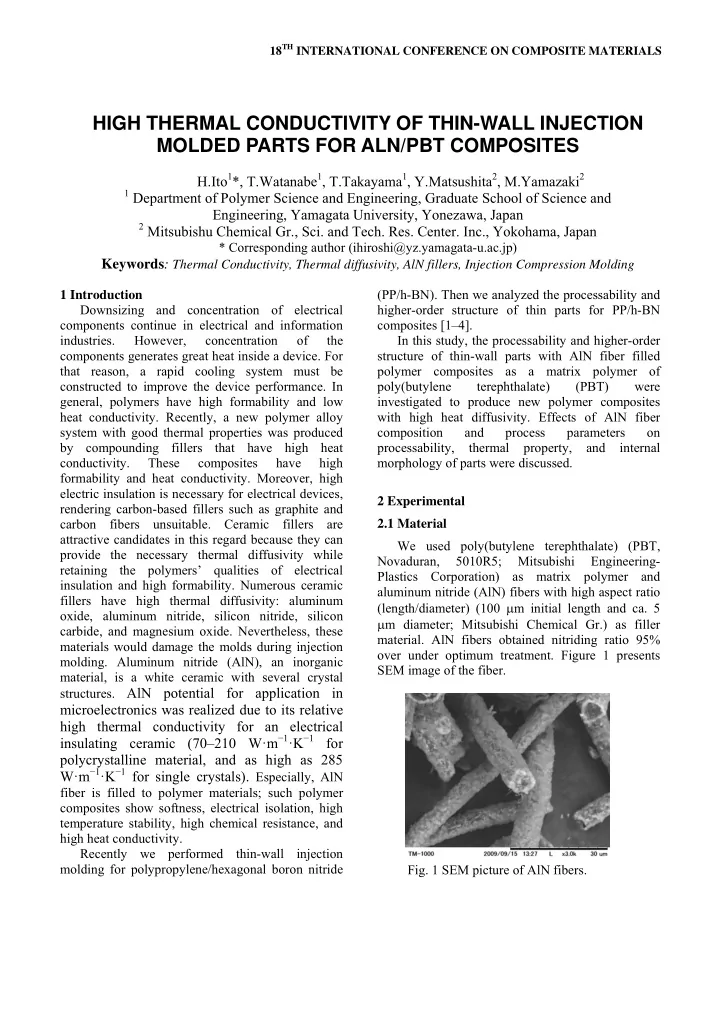
processability, thermal property, and internal conductivity. These composites have high morphology of parts were discussed. formability and heat conductivity. Moreover, high electric insulation is necessary for electrical devices, 2 Experimental rendering carbon-based fillers such as graphite and carbon fibers unsuitable. Ceramic fillers are 2.1 Material attractive candidates in this regard because they can We used poly(butylene terephthalate) (PBT, provide the necessary thermal diffusivity while Novaduran, 5010R5; Mitsubishi Engineering- retaining the polymers’ qualities of electrical Plastics Corporation) as matrix polymer and insulation and high formability. Numerous ceramic aluminum nitride (AlN) fibers with high aspect ratio fillers have high thermal diffusivity: aluminum (length/diameter) (100 μ m initial length and ca. 5 oxide, aluminum nitride, silicon nitride, silicon μ m diameter; Mitsubishi Chemical Gr.) as filler carbide, and magnesium oxide. Nevertheless, these material. AlN fibers obtained nitriding ratio 95% materials would damage the molds during injection over under optimum treatment. Figure 1 presents molding. Aluminum nitride (AlN), an inorganic SEM image of the fiber. material, is a white ceramic with several crystal structures. AlN potential for application in microelectronics was realized due to its relative high thermal conductivity for an electrical insulating ceramic (70–210 W·m − 1 ·K − 1 for polycrystalline material, and as high as 285 W·m − 1 ·K − 1 for single crystals). Especially, AlN fiber is filled to polymer materials; such polymer composites show softness, electrical isolation, high temperature stability, high chemical resistance, and high heat conductivity. Recently we performed thin-wall injection molding for polypropylene/hexagonal boron nitride Fig. 1 SEM picture of AlN fibers.

  2. pressure, the maximum injection pressure, and 2.2 Compounding, molding process and mold cavity thickness were, respectively, 265°C, 140°C, We compounded PBT and AlN using a twin- 50 MPa, 200 MPa, and 0.3 mm. The injection speed screw micro-compounding system (Imoto was selected to 300 mm/s. The compression stroke Seisakushi Co.) by compounding the temperature at as cavity open distance was varied at 0.5 and 2.0 260°C with compounding time at 10 min. The mm. The plunger position for compression reached compositions of AlN were 20 and 40 vol%. at 0.5 or 2.5 mm, and then the compression for A small electric injection-molding machine cavity started immediately. This means that (ELJECT AU3E; Nissei Plastic Industrial Co., Ltd.) compression delay time was 0 s. Figure 3 shows was used in this system for molding. In injection photographs of PBT/AlN composites products of molding of thin-wall plates, the injection unit injection compression molding. In ICM, the flow temperature, the mold temperature, the holding length increased and the composites filled perfectly pressure, the maximum injection pressure, and as compared with a common injection molding cavity thickness were, respectively, 265°C, 140°C, products (#4). At 20 vol%, the composites also filled 50 MPa, 200 MPa, and 0.3 or 1 mm. The injection in the cavity at all molding condition. speed was selected to 120 or 160 mm/s. Figure 2 shows photograph of PBT/AlN composites product. The flow length of molded parts decreased with increasing composition of AlN. At 1.0 mm thickness, the flow length of molded parts increased; then showed a full pack. #1 #2 #3 #4 Figure 3 Photographs of products of PBT/AlN ICM composites. #1: the compression stroke 0.5 mm & the plunger position for compression 2.5 mm #2: the compression stroke 2.0 mm & the plunger position for compression 0.5 mm #3: the compression stroke 2.0 mm & the plunger position for Figure 2 Photographs of products of PBT/AlN compression 2.5 mm composites. Cavity thickness is 0.3mm. #4: the compression stroke 0 mm (common injection molding) Injection speed is 120 mm/s. 2.3 Characteristic method Injection compression molding (ICM) was also We investigated the processability through the performed to improve the thermal properties of the flow length of the thin-wall plate. Thermal composites. In ICM process, the molecular properties of PBT/AlN composites were measured orientation inside molded parts was reduced as using modulated DSC and TGA measurements. compared with a common injection molding process. Thermal diffusivity of the thin plate along the One of research objects in this study is to improve thickness direction (ND direction) was measured thermal conductivity for thickness direction of using a temperature wave-analysis system. The molded parts. In this process, the injection unit higher-order structure of the thin plate was evaluated temperature, the mold temperature, the holding using wide angle X-ray diffraction (WAXD)

  3. measurements. We also observed filler distribution Therefore, the injection molded product revealed a and orientation inside cross sectional areas of structural distribution inside the cross-sectional area. products using scanning electron microscopy (SEM) The AlN orientation was observed directly using after freezing with liquid N 2 and splitting along the SEM. The polymer orientation is usually evaluated MD line. Tensile tests were conducted using a mini by optical retardation. However, the product was tensile testing machine after the thin plate was cut unclear; we evaluated the polymer orientation using into a dumbbell shape. the WAXD image. Figure 5 shows WAXD images of products of PBT/AlN composites. From the WAXD 3 Results and Discussion measurement, the flow direction of PBT molded We observed the cross-sectional area of the PBT product was aligned parallel to the meridian thin-wall product near the gate by SEM. Figure 4 direction of the WAXD image. The crystalline peak presents an SEM image of the cross-sectional area of was assigned to the equatorial direction if the the PBT thin-wall product near the gate, which molecular oriented to the flow direction. The peak contains 40 vol% AlN. The filler aligned along the intensity also concentrated to the equatorial position. polymer flow direction and laminar structure of However, the pattern became broader with PBT/AlN was observed. The filler orientation along increasing distance from the gate, indicating that the the MD axis was higher at the product edge than at pressure distribution in the cavity influenced the the product center. It was apparently equal to that of development of the higher-order structure. In general, the skin-shear-core layer inside the injection pressure in the cavity decreases downstream. The molding products. The AlN orientation near the polymer orientation similarly decreases downstream. surface became higher than that of the product The diffraction pattern of PBT/AlN composite center. The polymer flow near the cavity wall shows became broader than that of product PBT only. high shear stress attributable to rapid cooling. Effects of compounding AlN on mechanical FD ND Figure 4 SEM picture of the cross-sectional area of the PBT/ AlN composites. Figure 5 WAXD images of PBT/AlN composites. Injection speed is 120 mm/s. 3

Download Presentation
Download Policy: The content available on the website is offered to you 'AS IS' for your personal information and use only. It cannot be commercialized, licensed, or distributed on other websites without prior consent from the author. To download a presentation, simply click this link. If you encounter any difficulties during the download process, it's possible that the publisher has removed the file from their server.

Recommend


More recommend