SLIDE 1 Hardware Design with VHDL Combinational Circuit Design ECE 443 ECE UNM 1 (10/2/09) Combinational Circuit Design This slide set covers
- Derivation of efficient HDL description
- Operator sharing
- Functionality sharing
- Layout-related circuits
- General circuits
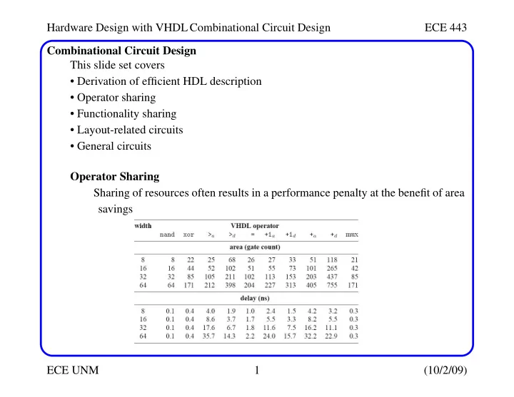
Operator Sharing Sharing of resources often results in a performance penalty at the benefit of area savings
SLIDE 2
Hardware Design with VHDL Combinational Circuit Design ECE 443 ECE UNM 2 (10/2/09) Operator Sharing Ideally, synthesis software can identify these opportunities automatically, but in prac- tice, this is rarely the case. There are usually lots of opportunities to share resources using the basic VHDL con- structs b/c in many cases, operations are mutually exclusive The value expressions in priority network and multiplexing network are mutu- ally exclusive in the sense that only one result is routed to the output Conditional signal assignment (same for if stmt) sig_name <= value_expr_1 when boolean_expr_1 else value_expr_2 when boolean_expr_2 else value_expr_3 when boolean_expr_3 else ... Selected signal assignment (same for case stmt) with select_expression select sig_name <= value_expr_1 when choice_1, value_expr_2 when choice_2, ... value_expr_n when choice_n;
SLIDE 3
Hardware Design with VHDL Combinational Circuit Design ECE 443 ECE UNM 3 (10/2/09) Operator Sharing If same operator is used in different expressions, it can be shared Example 1: Original code: r <= a+b when boolean_exp else a+c; Revised code: here the operands are routed, not the output of the adder src0 <= b when boolean_exp else c; r <= a + src0; Original: Area: 2 adders, 1 MUX, Delay: max(Tadder, Tboolean) + TMUX With Sharing: Area: 1 adders, 1 MUX, Delay: Tboolean + TMUX + Tadder
SLIDE 4
Hardware Design with VHDL Combinational Circuit Design ECE 443 ECE UNM 4 (10/2/09) Operator Sharing Example 2: Original code: process(a,b,c,d,...) begin if boolean_exp_1 then r <= a+b; elsif boolean_exp_2 then r <= a+c; else r <= d+1; end if end process; Revised code: process(a,b,c,d,...) begin if boolean_exp_1 then src0 <= a; src1 <= b;
SLIDE 5
Hardware Design with VHDL Combinational Circuit Design ECE 443 ECE UNM 5 (10/2/09) Operator Sharing elsif boolean_exp_2 then src0 <= a; src1 <= c; else src0 <= d; src1 <= "00000001"; -- MUX with constants can be end if; -- optimized by synthesis, end process; -- yielding more area savings r <= src0 + src1; Original: Area: 2 adders, 1 inc, 2 MUX With Sharing: Area: 1 adder, 4 MUX
SLIDE 6
Hardware Design with VHDL Combinational Circuit Design ECE 443 ECE UNM 6 (10/2/09) Operator Sharing Example 3: Original code: with sel select r <= a+b when "00", a+c when "01", d+1 when others; Revised code: with sel_exp select src0 <= a when "00"|"01", d when others; with sel_exp select src1 <= b when "00", c when "01", "00000001" when others; r <= src0 + src1;
SLIDE 7 Hardware Design with VHDL Combinational Circuit Design ECE 443 ECE UNM 7 (10/2/09) Operator Sharing Note that the revised implementation has longer delay because of:
- The increased number of cascaded components in some cases
- The restriction on the available parallelism in other cases
Original: Area: 2 adders, 1 inc, 1 MUX With Sharing: Area: 1 adder, 2 MUX Note that in the revised scheme, the sel exp Boolean logic MUST be evaluated first before the addition takes place -- this is not the case in the original version
SLIDE 8
Hardware Design with VHDL Combinational Circuit Design ECE 443 ECE UNM 8 (10/2/09) Operator Sharing Example 4: Original code: process(a,b,c,d,...) begin if boolean_exp then x <= a + b; y <= (others=>’0’); else x <= (others=>’1’); y <= c + d; end if; end process; Original: Area: 2 adders, 2 MUX
SLIDE 9
Hardware Design with VHDL Combinational Circuit Design ECE 443 ECE UNM 9 (10/2/09) Operator Sharing Revised code: process(a,b,c,d,...) begin if boolean_exp then src0 <= a; src1 <= b; x <= sum; y <= (others=>’0’); else src0 <= c; src1 <= d; x <= (others=>’1’); y <= sum; end if; end process; sum <= src0 + src1;
SLIDE 10 Hardware Design with VHDL Combinational Circuit Design ECE 443 ECE UNM 10 (10/2/09) Operator Sharing Worst case situation in which operator has no common sources or destinations Is the sharing worthwhile in this case? 1 adder saved in original version but 2 MUX added in revised scheme It depends on the size of the adder -- if optimized for speed, then it can be signif- icantly larger than 2 MUX Summary
- Merit of sharing depends on the complexity of the operator and the routing circuit
- Complex operators provide a lot of area savings
- Cost is increased propagation delay because of serial operation
With Sharing: Area: 1 adders, 4 MUX
SLIDE 11
Hardware Design with VHDL Combinational Circuit Design ECE 443 ECE UNM 11 (10/2/09) Functionality Sharing A large circuit such as a microcontroller includes a lot of functions Several functions may be related and can share a common circuit Identifying these opportunities is more difficult and is something synthesis software can NOT do Done in an ad hoc manner by designer and is based on his/her expertise Consider add-sub circuit Straightforward translation into VHDL: library ieee; use ieee.std_logic_1164.all; use ieee.numeric_std.all; entity addsub is
SLIDE 12
Hardware Design with VHDL Combinational Circuit Design ECE 443 ECE UNM 12 (10/2/09) Functionality Sharing port ( a,b: in std_logic_vector(7 downto 0); ctrl: in std_logic; r: out std_logic_vector(7 downto 0) ); end addsub; architecture direct_arch of addsub is signal src0, src1, sum: signed(7 downto 0); begin src0 <= signed(a); src1 <= signed(b); sum <= src0 + src1 when ctrl=’0’ else src0 - src1; r <= std_logic_vector(sum); end direct_arch;
SLIDE 13
Hardware Design with VHDL Combinational Circuit Design ECE 443 ECE UNM 13 (10/2/09) Functionality Sharing This version is translated such that it includes an adder, subtractor and MUX As we know, in 2’s compliment, subtraction is implemented as a + b + 1 architecture shared_arch of addsub is signal src0, src1, sum: signed(7 downto 0); signal cin: signed(0 downto 0); -- carry-in bit begin src0 <= signed(a); src1 <= signed(b) when ctrl=’0’ else signed(not b); cin <= "0" when ctrl=’0’ else "1"; sum <= src0 + src1 + cin; r <= std_logic_vector(sum); end shared_arch;
SLIDE 14
Hardware Design with VHDL Combinational Circuit Design ECE 443 ECE UNM 14 (10/2/09) Functionality Sharing The ’+ 1’ is implemented by setting the carry-in bit to ’1’ of the adder Most synthesis software should deduce that the ’+ cin’ is one bit and can be imple- mented in this fashion Alternatively, you can manually describe the carry-in in the adder by adding an extra bit to the adder and operands Original operands a7a6a5a4a3a2a1a0 and b7b6b5b4b3b2b1b0 New operands a7a6a5a4a3a2a1a01 and b7b6b5b4b3b2b1b0cin
SLIDE 15
Hardware Design with VHDL Combinational Circuit Design ECE 443 ECE UNM 15 (10/2/09) Functionality Sharing After the addition, discard the low order bit architecture manual_carry_arch of addsub is signal src0, src1, sum: signed(8 downto 0); signal b_tmp: std_logic_vector(7 downto 0); signal cin: std_logic; -- carry-in bit begin src0 <= signed(a & ’1’); b_tmp <= b when ctrl=’0’ else not b; cin <= ’0’ when ctrl=’0’ else ’1’; src1 <= signed(b_tmp & cin); sum <= src0 + src1; r <= std_logic_vector(sum(8 downto 1)); end manual_carry_arch;
SLIDE 16
Hardware Design with VHDL Combinational Circuit Design ECE 443 ECE UNM 16 (10/2/09) Functionality Sharing As we know, ieee.numeric_std provides signed and unsigned, with signed in 2’s com- plement format Here, addition and subtraction operations are identical and therefore, the same hard- ware can be used for either data type
SLIDE 17
Hardware Design with VHDL Combinational Circuit Design ECE 443 ECE UNM 17 (10/2/09) Functionality Sharing Unfortunately, this is not true for the relational operators, and therefore we need to craft a control signal into the VHDL code library ieee; use ieee.std_logic_1164.all; use ieee.numeric_std.all; entity comp2mode is port( a,b: in std_logic_vector(7 downto 0); mode: in std_logic; agtb: out std_logic ); end comp2mode; architecture direct_arch of comp2mode is signal agtb_signed, agtb_unsigned: std_logic; begin
SLIDE 18
Hardware Design with VHDL Combinational Circuit Design ECE 443 ECE UNM 18 (10/2/09) Functionality Sharing agtb_signed <= ’1’ when signed(a) > signed(b) else ’0’; agtb_unsigned <= ’1’ when unsigned(a) > unsigned(b) else ’0’; agtb <= agtb_unsigned when (mode=’0’) else agtb_signed; end direct_arch; To create an opportunity for sharing, we need to handle the sign bit separately for signed operands If the sign bits are different, then the positive number is larger for signed If they are the same, compare the n-1 bits (without MSB) using normal comparison Consider 1111 (-1), 1100 (-4), 1001(-7) -- after removing the MSB (sign bit) 111 > 100 > 001 Which is consistent with -1 > -4 > -7, so we can share the LSB compare logic
SLIDE 19 Hardware Design with VHDL Combinational Circuit Design ECE 443 ECE UNM 19 (10/2/09) Functionality Sharing architecture shared_arch of comp2mode is signal a1_b0, agtb_mag: std_logic; begin a1_b0 <= ’1’ when a(7)=’1’ and b(7)=’0’ else ’0’; agtb_mag <= ’1’ when a(6 downto 0) > b(6 downto 0) else ’0’; agtb <= agtb_mag when (a(7)=b(7)) else a1_b0 when mode=’0’ else -- unsigned mode not a1_b0; -- signed mode end shared_arch; Rules are
- If a and b have same sign bit, compare in regular fashion
- If a’s sign bit is ’1’ and b’s sign bit is ’0’, a is greater than b when in unsigned
mode and b is greater than a in signed mode
- If a’s sign bit is ’0’ and b’s sign bit is ’1’, reverse the previous result
New version is about 1/2 size of dual mode version
SLIDE 20
Hardware Design with VHDL Combinational Circuit Design ECE 443 ECE UNM 20 (10/2/09) Functionality Sharing Assume we need a full comparator, i.e., one that provides greater-than, equal-to and less-than -- straightforward approach library ieee; use ieee.std_logic_1164.all; entity comp3 is port( a,b: in std_logic_vector(15 downto 0); agtb, altb, aeqb: out std_logic ); end comp3 ; architecture direct_arch of comp3 is begin agtb <= ’1’ when a > b else ’0’; altb <= ’1’ when a < b else ’0’; aeqb <= ’1’ when a = b else ’0’; end direct_arch;
SLIDE 21 Hardware Design with VHDL Combinational Circuit Design ECE 443 ECE UNM 21 (10/2/09) Functionality Sharing An obvious change is to share the resources of two of the compares to derive the third Another optimization is to recognize that the equal-to comparator is faster and smaller than the other two architecture share2_arch of comp3 is signal eq, lt: std_logic; begin eq <= ’1’ when a = b else ’0’; lt <= ’1’ when a < b else ’0’; aeqb <= eq; altb <= lt; agtb <= not (eq or lt); end share2_arch; Text covers a
- absolute difference circuit
- three function barrel shifter circuit
SLIDE 22 Hardware Design with VHDL Combinational Circuit Design ECE 443 ECE UNM 22 (10/2/09) Layout-Related Circuits After synthesis, placement and routing will derive the actual physical layout of a dig- ital circuit on a silicon chip VHDL cannot specify the exact layout, but it can control the general "shape" In general, "square" or 2-D circuits are better than a 1-D cascading-chain
- \Conditional signal assignment/if statement form a single "horizontal" cascading
chain
- Selected signal assignment/case statement form a large "vertical" mux
- Neither is ideal
1-D has long delay Better, 2-D has shorter delay
SLIDE 23
Hardware Design with VHDL Combinational Circuit Design ECE 443 ECE UNM 23 (10/2/09) Layout-Related Circuits Consider the reduced-xor circuit (covered before), in which all input bits of the oper- and are XOR’ed to produce the output The previous 1-D schematic is described as follows library ieee; use ieee.std_logic_1164.all; entity reduced_xor is port( a: in std_logic_vector(7 downto 0); y: out std_logic ); end reduced_xor; architecture cascade1_arch of reduced_xor is begin y <= a(0) xor a(1) xor a(2) xor a(3) xor a(4) xor a(5) xor a(6) xor a(7); end cascade1_arch;
SLIDE 24
Hardware Design with VHDL Combinational Circuit Design ECE 443 ECE UNM 24 (10/2/09) Layout-Related Circuits We can also use an 8-bit internal signal p to represent intermediate results architecture cascade2_arch of reduced_xor is signal p: std_logic_vector(7 downto 0); begin p(0) <= ’0’ xor a(0); p(1) <= p(0) xor a(1); p(2) <= p(1) xor a(2); p(3) <= p(2) xor a(3); p(4) <= p(3) xor a(4); p(5) <= p(4) xor a(5); p(6) <= p(5) xor a(6); p(7) <= p(6) xor a(7); y <= p(7); end cascade2_arch; The repetitive nature allows for a more compact vector form as shown below
SLIDE 25 Hardware Design with VHDL Combinational Circuit Design ECE 443 ECE UNM 25 (10/2/09) Layout-Related Circuits architecture cascade_compact_arch of reduced_xor is constant WIDTH: integer := 8; signal p: std_logic_vector(WIDTH-1 downto 0); begin p <= (p(WIDTH-2 downto 0) & ’0’) xor a; y <= p(WIDTH-1); end cascade_compact_arch; Although this design uses the minimal number of XOR gates, it suffers from long propagation delay Although the synthesis tool is likely to produce a 2-D structure given the simplicity
- f this circuit, the following is one way to guarantee it
architecture tree_arch of reduced_xor is begin y <= ((a(7) xor a(6)) xor (a(5) xor a(4))) xor ((a(3) xor a(2)) xor (a(1) xor a(0))); end tree_arch;
SLIDE 26 Hardware Design with VHDL Combinational Circuit Design ECE 443 ECE UNM 26 (10/2/09) Layout-Related Circuits Comparison of n-input reduced xor
Area: (n-1) xor gates, Delay: (n-1), Coding: easy to modify (scale)
Area: (n-1) xor gates, Delay: log2n, Coding: not so easy to modify Consider a reduced-xor-vector circuit Here, all combinations of the lower bits of the input signal are xor’ed to produce 8
The straightforward (no sharing) implementation is given below
SLIDE 27
Hardware Design with VHDL Combinational Circuit Design ECE 443 ECE UNM 27 (10/2/09) Layout-Related Circuits library ieee; use ieee.std_logic_1164.all; entity reduced_xor_vector is port( a: in std_logic_vector(7 downto 0); y: out std_logic_vector(7 downto 0) ); end reduced_xor_vector; architecture direct_arch of reduced_xor_vector is begin y(0) <= a(0); y(1) <= a(1) xor a(0); y(2) <= a(2) xor a(1) xor a(0); y(3) <= a(3) xor a(2) xor a(1) xor a(0); y(4) <= a(4) xor a(3) xor a(2) xor a(1) xor a(0); y(5) <= a(5) xor a(4) xor a(3) xor a(2) xor a(1) xor a(0);
SLIDE 28
Hardware Design with VHDL Combinational Circuit Design ECE 443 ECE UNM 28 (10/2/09) Layout-Related Circuits y(6) <= a(6) xor a(5) xor a(4) xor a(3) xor a(2) xor a(1)xor a(0); y(7) <= a(7) xor a(6) xor a(5) xor a(4) xor a(3) xor a(2)xor a(1) xor a(0); end direct_arch; This requires 28 xor gates if implemented un-optimized -- there are lots of common sub-expressions that can be shared Code that shares is very similar to the reduced-xor code given earlier except all inter- mediate results are used as outputs architecture shared1_arch of reduced_xor_vector is signal p: std_logic_vector(7 downto 0); begin p(0) <= a(0); p(1) <= p(0) xor a(1); p(2) <= p(1) xor a(2); p(3) <= p(2) xor a(3);
SLIDE 29
Hardware Design with VHDL Combinational Circuit Design ECE 443 ECE UNM 29 (10/2/09) Layout-Related Circuits p(4) <= p(3) xor a(4); p(5) <= p(4) xor a(5); p(6) <= p(5) xor a(6); p(7) <= p(6) xor a(7); y <= p; end shared1_arch; As before, the pattern of assignments can be coded more efficiently architecture shared_compact_ar of reduced_xor_vector is constant WIDTH: integer := 8; signal p: std_logic_vector(WIDTH-1 downto 0); begin p <= (p(WIDTH-2 downto 0) & ’0’) xor a; y <= p; end shared_compact_ar; All of these designs specify a 1-D structure, with the critical path to y(7) Text gives version with parenthesis to force 2-D tree-type design
SLIDE 30
Hardware Design with VHDL Combinational Circuit Design ECE 443 ECE UNM 30 (10/2/09) Layout-Related Circuits An ad hoc version that reduces both propagation delay to 3 gates AND uses only 12 xor gates architecture optimal_tree_arch of reduced_xor_vector is signal p01, p23, p45, p67, p012, p0123, p456, p4567: std_logic; begin p01 <= a(0) xor a(1); p23 <= a(2) xor a(3); p45 <= a(4) xor a(5); p67 <= a(6) xor a(7); p012 <= p01 xor a(2); p0123 <= p01 xor p23; p456 <= p45 xor a(6); p4567 <= p45 xor p67; y(0) <= a(0); y(1) <= p01; y(2) <= p012; y(3) <= p0123;
SLIDE 31
Hardware Design with VHDL Combinational Circuit Design ECE 443 ECE UNM 31 (10/2/09) Layout-Related Circuits y(4) <= p0123 xor a(4); y(5) <= p0123 xor p45; y(6) <= p0123 xor p456; y(7) <= p0123 xor p4567; end optimal_tree_arch;
SLIDE 32 Hardware Design with VHDL Combinational Circuit Design ECE 443 ECE UNM 32 (10/2/09) Layout-Related Circuits Comparison of n-input reduced-xor-vector
Area: (n-1) xor gates, Delay: (n-1), Coding: easy to modify (scale)
Area: O(n2) xor gates, Delay: log2n, Coding: not so easy to modify
Area: O(nlog2n) xor gates, Delay: log2n, Coding: difficult to modify Unlike the previous example, synthesis is not able to convert cascading chain to the
- ptimal tree (parallel-prefix)
Next consider a barrel shifter -- direct implementation library ieee; use ieee.std_logic_1164.all; entity rotate_right is port( a: in std_logic_vector(7 downto 0);
SLIDE 33
Hardware Design with VHDL Combinational Circuit Design ECE 443 ECE UNM 33 (10/2/09) Layout-Related Circuits (Barrel shifter) amt: in std_logic_vector(2 downto 0); y: out std_logic_vector(7 downto 0) ); end rotate_right; architecture direct_arch of rotate_right is begin with amt select y<= a when "000", a(0) & a(7 downto 1) when "001", a(1 downto 0) & a(7 downto 2) when "010", a(2 downto 0) & a(7 downto 3) when "011", a(3 downto 0) & a(7 downto 4) when "100", a(4 downto 0) & a(7 downto 5) when "101", a(5 downto 0) & a(7 downto 6) when "110", a(6 downto 0) & a(7) when others; -- 111 end direct_arch;
SLIDE 34
Hardware Design with VHDL Combinational Circuit Design ECE 443 ECE UNM 34 (10/2/09) Layout-Related Circuits The barrel shifter rotates the input a by the amount specified, from 0 to 7 rotates The code is realized using eight 1-bit 8-to-1 MUXs
SLIDE 35 Hardware Design with VHDL Combinational Circuit Design ECE 443 ECE UNM 35 (10/2/09) Layout-Related Circuits Problems with this include
- Wide MUXs cannot be effectively mapped to certain device technologies
- Input wires, a, route to all MUXs, so loading and congestion grows as O(n2)
- The ’single narrow strip’ shape makes place and route difficult
Better to do the wiring in levels In each level, each bit of the amt signal determines if we rotate or pass through Note that the rotate amounts are different depending on the bit’s position After passing through all three levels, the number of rotations performed is equal to the sum of those performed at each level amt(2)*22 + amt(1)*21 + amt(0)*20
SLIDE 36 Hardware Design with VHDL Combinational Circuit Design ECE 443 ECE UNM 36 (10/2/09) Layout-Related Circuits architecture multi_level_arch of rotate_right is signal le0_out, le1_out, le2_out: std_logic_vector(7 downto 0); begin
- - level 0, shift 0 or 1 bit
le0_out <= a(0) & a(7 downto 1) when amt(0)=’1’ else a;
- - level 1, shift 0 or 2 bits
le1_out <= le0_out(1 downto 0) & le0_out(7 downto 2) when amt(1)=’1’ else le0_out;
- - level 2, shift 0 or 4 bits
le2_out <= le1_out(3 downto 0) & le1_out(7 downto 4) when amt(2)=’1’ else le1_out; y <= le2_out; end multi_level_arch;
SLIDE 37 Hardware Design with VHDL Combinational Circuit Design ECE 443 ECE UNM 37 (10/2/09) Layout-Related Circuits Comparison for n-bit shifter
n n-to-1 MUX Vertical strip with O(n2) input wiring Code not so easy to modify
n*log2n 2-to-1 MUX (8 2-to-1 MUXs at each level for a total of 24) Rectangular shaped Code easier to modify General Examples
- Gray code counter
- Signed addition with status
- Simple combinational multiplier
Gray code is a special sequence of values where only one bit changes in any two suc- cessive code.
SLIDE 38
Hardware Design with VHDL Combinational Circuit Design ECE 443 ECE UNM 38 (10/2/09) Gray Code Thus it minimizes the number of transitions that a signal switches between succes- sive words Need to implement the gray code incrementer on the right Straightforward way is to translate the table into a selected signal assignment stmt
SLIDE 39
Hardware Design with VHDL Combinational Circuit Design ECE 443 ECE UNM 39 (10/2/09) Gray Code library ieee; use ieee.std_logic_1164.all; use ieee.numeric_std.all; entity g_inc is port( g: in std_logic_vector(3 downto 0); g1: out std_logic_vector(3 downto 0) ); end g_inc ; architecture table_arch of g_inc is begin with g select g1 <= "0001" when "0000", "0011" when "0001", "0010" when "0011", "0110" when "0010", "0111" when "0110",
SLIDE 40
Hardware Design with VHDL Combinational Circuit Design ECE 443 ECE UNM 40 (10/2/09) Gray Code "0101" when "0111", "0100" when "0101", "1100" when "0100", "1101" when "1100", "1111" when "1101", "1110" when "1111", "1010" when "1110", "1011" when "1010", "1001" when "1011", "1000" when "1001", "0000" when others; -- "1000" end table_arch; Although this VHDL code is simple, it is not scalable b/c revisions take on order O(n2) Unfortunately, there is no easy algorithm to derive the next Gray code directly However, an algorithm does exist to convert between binary and Gray code, and therefore one implementation is to use a binary incrementer
SLIDE 41
Hardware Design with VHDL Combinational Circuit Design ECE 443 ECE UNM 41 (10/2/09) Gray Code So the algorithm is to 1) convert a Gray code to binary, 2) increment binary and 3) covert back The conversion is based on the following The ith bit (gi) of the Gray code word is ’1’ if the ith bit and (i + 1)th bit, i.e., bi and bi+1 of the corresponding binary word are different gi bi bi
1 +
⊕ = Binary to Gray bi gi bi
1 +
⊕ = Gray to Binary Note recursive expansion is possible Very similar to reduced-xor-vector
SLIDE 42 Hardware Design with VHDL Combinational Circuit Design ECE 443 ECE UNM 42 (10/2/09) Gray Code architecture compact_arch of g_inc is constant WIDTH: integer := 4; signal b, b1: std_logic_vector(WIDTH-1 downto 0); begin
b <= g xor (’0’ & b(WIDTH-1 downto 1));
b1 <= std_logic_vector((unsigned(b)) + 1);
g1<= b1 xor (’0’ & b1(WIDTH-1 downto 1)); end compact_arch; This code is independent of the input size (revision time O(1)) and uses a binary adder (of which there are many to choose from!)
SLIDE 43 Hardware Design with VHDL Combinational Circuit Design ECE 443 ECE UNM 43 (10/2/09) Signed Addition with Status The default ’+’ VHDL operator does not allow for status signals Common status signals reflecting the result of the addition include
- zero: Is the result 0?
- sign: What is the sign of the result?
- overflow: Did the result overflow?
Also, carry signals (carry in and out) pass information between successive additions Needed, for example, when you build a 64-bit adder from 8-bit adders Given these status signals, it is important to note that overflow must be checked first because the other status signals are invalid in this case The following deductions can be made
- If the two operands have different sign bits, then overflow is NOT possible
- If the two operands and the result have the same sign, then overflow did not occur
- If the two operands have the same sign but the result has a different sign, overflow
- ccurred
SLIDE 44 Hardware Design with VHDL Combinational Circuit Design ECE 443 ECE UNM 44 (10/2/09) Signed Addition with Status The following logic expression captures the last condition, with sa, sb and ss repre- senting the signs of the a and b operands and the sign of the sum, s Note that zero may be true when it shouldn’t be if overflow occurred, e.g., summing "1000" and "1000" using a 4-bit adder produces "0000" Similar arguments hold for sign -- sign of the above is ’0’ but it should be ’1’, there- fore, if overflow occurs, then the sign signal should be inverted The carry_in and carry_out signals are appended to the right and left, resp. library ieee; use ieee.std_logic_1164.all; use ieee.numeric_std.all; entity adder_status is port ( a,b: in std_logic_vector(7 downto 0);
sa sb ss
) sa sb ss
) + =
SLIDE 45 Hardware Design with VHDL Combinational Circuit Design ECE 443 ECE UNM 45 (10/2/09) Signed Addition with Status cin: in std_logic; sum: out std_logic_vector(7 downto 0); cout, zero, overflow, sign: out std_logic ); end adder_status; architecture arch of adder_status is signal a_ext, b_ext, sum_ext: signed(9 downto 0); signal ovf: std_logic; alias sign_a: std_logic is a_ext(8); alias sign_b: std_logic is b_ext(8); alias sign_s: std_logic is sum_ext(8); begin
- - bit extend the operands on both sides
a_ext <= signed(’0’ & a & ’1’); b_ext <= signed(’0’ & b & cin); sum_ext <= a_ext + b_ext;
SLIDE 46 Hardware Design with VHDL Combinational Circuit Design ECE 443 ECE UNM 46 (10/2/09) Signed Addition with Status
- vf <= (sign_a and sign_b and (not sign_s)) or
((not sign_a) and (not sign_b) and sign_s); cout <= sum_ext(9);
- - Invert sign if overflow occurred
sign <= sum_ext(8) when ovf=’0’ else not sum_ext(8);
- - zero is invalid is overflow occurred
zero <= ’1’ when (sum_ext(8 downto 1)=0 and ovf=’0’) else ’0’;
sum <= std_logic_vector(sum_ext(8 downto 1)); end arch;
SLIDE 47 Hardware Design with VHDL Combinational Circuit Design ECE 443 ECE UNM 47 (10/2/09) Simple Combinational Multiplier A simple multiplier can be constructed using first principles Simple algorithm:
- Multiply the digits of the multiplier, b3b2b1b0 by the multiplicand by A, one at a
time to obtain b3*A, b2*A, b1*A and b0*A Given bi can only be ’0’ or ’1’, the product can only be ’0’ or A Multiplication is performed using the and operation, i.e., bi*A = (a3bi, a2bi, a1bi, a0bi)
SLIDE 48 Hardware Design with VHDL Combinational Circuit Design ECE 443 ECE UNM 48 (10/2/09) Simple Combinational Multiplier Simple algorithm:
- Shift bi*A to the left i positions
- Add the shifted bi*A terms to obtain the final product
library ieee; use ieee.std_logic_1164.all; use ieee.numeric_std.all; entity mult8 is port( a, b: in std_logic_vector(7 downto 0); y: out std_logic_vector(15 downto 0) ); end mult8; architecture comb1_arch of mult8 is constant WIDTH: integer:=8; signal au, bv0, bv1, bv2, bv3, bv4, bv5, bv6, bv7: unsigned(WIDTH-1 downto 0);
SLIDE 49
Hardware Design with VHDL Combinational Circuit Design ECE 443 ECE UNM 49 (10/2/09) Simple Combinational Multiplier signal p0,p1,p2,p3,p4,p5,p6,p7,prod: unsigned(2*WIDTH-1 downto 0); begin au <= unsigned(a); bv0 <= (others=>b(0)); bv1 <= (others=>b(1)); bv2 <= (others=>b(2)); bv3 <= (others=>b(3)); bv4 <= (others=>b(4)); bv5 <= (others=>b(5)); bv6 <= (others=>b(6)); bv7 <= (others=>b(7)); p0 <="00000000" & (bv0 and au); p1 <="0000000" & (bv1 and au) & "0"; p2 <="000000" & (bv2 and au) & "00"; p3 <="00000" & (bv3 and au) & "000"; p4 <="0000" & (bv4 and au) & "0000";
SLIDE 50
Hardware Design with VHDL Combinational Circuit Design ECE 443 ECE UNM 50 (10/2/09) Simple Combinational Multiplier p5 <="000" & (bv5 and au) & "00000"; p6 <="00" & (bv6 and au) & "000000"; p7 <="0" & (bv7 and au) & "0000000"; prod <= ((p0+p1)+(p2+p3))+((p4+p5)+(p6+p7)); y <= std_logic_vector(prod); end comb1_arch; See text for alternative architecture, as well as examples of a Hamming distance cir- cuit and programmable priority encoder