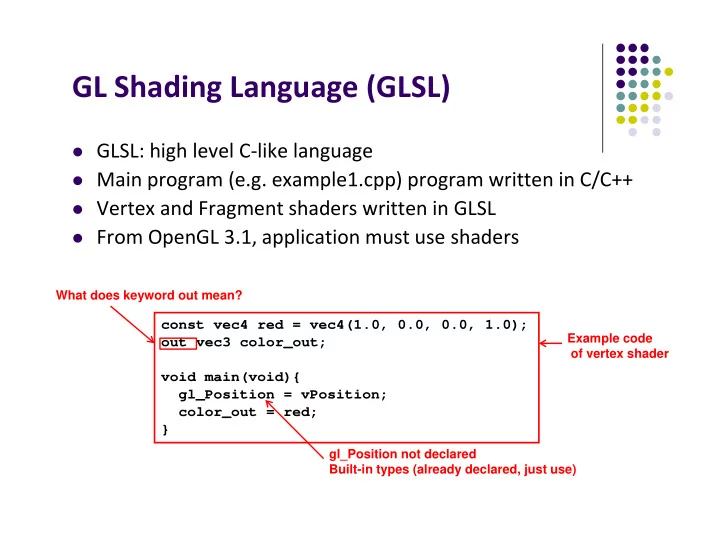
GL Shading Language (GLSL) GLSL: high level C like language Main - - PowerPoint PPT Presentation

gl shading language glsl
SMART_READER_LITE
LIVE PREVIEW

GL Shading Language (GLSL) GLSL: high level C like language Main - - PowerPoint PPT Presentation

GL Shading Language (GLSL) GLSL: high level C like language Main program (e.g. example1.cpp) program written in C/C++ Vertex and Fragment shaders written in GLSL From OpenGL 3.1, application must use shaders What does keyword


slide-1
SLIDE 1

 GLSL: high level C‐like language  Main program (e.g. example1.cpp) program written in C/C++  Vertex and Fragment shaders written in GLSL  From OpenGL 3.1, application must use shaders

const vec4 red = vec4(1.0, 0.0, 0.0, 1.0);

  • ut vec3 color_out;

void main(void){ gl_Position = vPosition; color_out = red; }

GL Shading Language (GLSL)

Example code

  • f vertex shader

gl_Position not declared Built-in types (already declared, just use) What does keyword out mean?

slide-2
SLIDE 2

 Variable declared out in vertex shader can be declared as in in

fragment shader and used

 Why? To pass result of vertex shader calculation to fragment

shader

const vec4 red = vec4(1.0, 0.0, 0.0, 1.0);

  • ut vec3 color_out;

void main(void){ gl_Position = vPosition; color_out = red; }

Passing values

Vertex Shader in

  • ut

From main program To fragment shader

Fragment Shader in

  • ut

From Vertex shader To framebuffer in vec3 color_out; void main(void){ // can use color_out here. }

Fragment shader Vertex shader

slide-3
SLIDE 3

 C types: int, float, bool  GLSL types:

float vec2: e.g. (x,y) // vector of 2 floats

float vec3: e.g. (x,y,z) or (R,G,B) // vector of 3 floats

float vec4: e.g. (x,y,z,w) // vector of 4 floats

Const float vec4 red = vec4(1.0, 0.0, 0.0, 1.0);

  • ut float vec3 color_out;

void main(void){ gl_Position = vPosition; color_out = red; }

 Also:

 int (ivec2, ivec3, ivec4) and  boolean (bvec2, bvec3,bvec4)

Data Types

Vertex shader

C++ style constructors

slide-4
SLIDE 4

Data Types

 Matrices: mat2, mat3, mat4

 Stored by columns  Standard referencing m[row][column]

 Matrices and vectors are basic types  can be passed in and out from GLSL functions  E.g

mat3 func(mat3 a)

 No pointers in GLSL  Can use C structs that are copied back from functions

slide-5
SLIDE 5

Qualifiers

 GLSL has many C/C++ qualifiers such as const  Supports additional ones  Variables can change

 Once per vertex  Once per fragment  Once per primitive (e.g. triangle)  At any time in the application

 Example: variable vPosition may be assigned once per vertex

Primitive Vertex

const vec4 red = vec4(1.0, 0.0, 0.0, 1.0);

  • ut vec3 color_out;

void main(void){ gl_Position = vPosition; color_out = red; }

slide-6
SLIDE 6

Operators and Functions

 Standard C functions

 Trigonometric: cos, sin, tan, etc  Arithmetic: log, min, max, abs, etc  Normalize, reflect, length

 Overloading of vector and matrix types

mat4 a; vec4 b, c, d; c = b*a; // a column vector stored as a 1d array d = a*b; // a row vector stored as a 1d array

slide-7
SLIDE 7

Swizzling and Selection

 Can refer to array elements by element using [] or

selection (.) operator with

 x, y, z, w  r, g, b, a  s, t, p, q  vec4 a;  a[2], a.b, a.z, a.p are the same

 Swizzling operator lets us manipulate components

a.yz = vec2(1.0, 2.0);

slide-8
SLIDE 8

Computer Graphics (CS 4731) Lecture 7: Building 3D Models Prof Emmanuel Agu

Computer Science Dept. Worcester Polytechnic Institute (WPI)

slide-9
SLIDE 9

3D Applications

 2D points: (x,y) coordinates  3D points: have (x,y,z) coordinates

slide-10
SLIDE 10

Setting up 3D Applications: Main Steps

 Programming 3D similar to 2D

1.

Load representation of 3D object into data structure

2.

Draw 3D object

3.

Set up Hidden surface removal: Correctly determine

  • rder in which primitives (triangles, faces) are

rendered (e.g Blocked faces NOT drawn)

Each vertex has (x,y,z) coordinates. Store as vec3 NOT vec2

slide-11
SLIDE 11

 Vertex (x,y,z) positions specified on coordinate system  OpenGL uses right hand coordinate system

3D Coordinate Systems

x Y + z Right hand coordinate system Tip: sweep fingers x‐y: thumb is z x Left hand coordinate system

  • Not used in OpenGL

+ z Y

slide-12
SLIDE 12

Generating 3D Models: GLUT Models

 Make GLUT 3D calls in OpenGL program to generate vertices

describing different shapes (Restrictive?)

 Two types of GLUT models:

Wireframe Models

Solid Models

Solid m odels W irefram e m odels

slide-13
SLIDE 13

3D Modeling: GLUT Models

 Basic Shapes

Cone: glutWireCone( ), glutSolidCone( )

Sphere: glutWireSphere( ), glutSolidSphere( )

Cube: glutWireCube( ), glutSolidCube( )

 More advanced shapes:

Newell Teapot: (symbolic)

Dodecahedron, Torus

Torus Cone Sphere New ell Teapot

slide-14
SLIDE 14

3D Modeling: GLUT Models

 Glut functions under the hood

 generate sequence of points that define a shape

 Generated vertices and faces passed to OpenGL for rendering

 Example: glutWireCone generates sequence of vertices,

and faces defining cone and connectivity

glutWireCone OpenGL program (renders cone) vertices, and faces defining cone

slide-15
SLIDE 15

Polygonal Meshes

 Modeling with GLUT shapes (cube, sphere, etc) too restrictive  Difficult to approach realism. E.g. model a horse  Preferred way is using polygonal meshes:  Collection of polygons, or faces, that form “skin” of object  More flexible, represents complex surfaces better  Examples:  Human face  Animal structures  Furniture, etc

Each face of mesh is a polygon

slide-16
SLIDE 16

Polygonal Mesh Example

Mesh ( w irefram e) Sm oothed Out w ith Shading ( later)

slide-17
SLIDE 17

Polygonal Meshes

 Meshes now standard in graphics  OpenGL Good at drawing polygons, triangles  Mesh = sequence of polygons forming thin skin around object  Simple meshes exact. (e.g barn)  Complex meshes approximate (e.g. human face)

slide-18
SLIDE 18

Different Resolutions of Same Mesh

Original: 424,000 triangles 60,000 triangles (14%). 1000 triangles (0.2%) (courtesy of Michael Garland and Data courtesy of Iris Development.)

slide-19
SLIDE 19

Representing a Mesh

 Consider a mesh  There are 8 vertices and 12 edges

 5 interior polygons  6 interior (shared) edges (shown in orange)

 Each vertex has a location vi = (xi yi zi)

v1 v2 v7 v6 v8 v5 v4 v3 e1 e8 e3 e2 e11 e6 e7 e10 e5 e4 e9 e12

slide-20
SLIDE 20

Simple Representation

 Define each polygon by (x,y,z) locations of its vertices  OpenGL code

vertex[i] = vec3(x1, y1, z1); vertex[i+1] = vec3(x6, y6, z6); vertex[i+2] = vec3(x7, y7, z7); i+=3;

slide-21
SLIDE 21

Issues with Simple Representation

 Declaring face f1  Declaring face f2  Inefficient and unstructured

 Repeats: vertices v1 and v7 repeated while declaring f1 and f2  Shared vertices shared declared multiple times  Delete vertex? Move vertex? Search for all occurences of vertex

vertex[i] = vec3(x1, y1, z1); vertex[i+1] = vec3(x7, y7, z7); vertex[i+2] = vec3(x8, y8, z8); vertex[i+3] = vec3(x6, y6, z6);

v1 v2 v7 v6 v8 v5 v4 v3

vertex[i] = vec3(x1, y1, z1); vertex[i+1] = vec3(x2, y2, z2); vertex[i+2] = vec3(x7, y7, z7);

f2 f1

slide-22
SLIDE 22

Geometry vs Topology

 Better data structures separate geometry from topology

 Geometry: (x,y,z) locations of the vertices  Topology: How vertices and edges are connected  Example:

 A polygon is ordered list of vertices  An edge connects successive pairs of vertices

 Topology holds even if geometry changes (vertex moves)

v1 v2 v7 v6 v8 v5 v4 v3 f2 f1

Example: even if we move (x,y,z) location of v1, v1 still connected to v6, v7 and v2

v1

slide-23
SLIDE 23

Polygon Traversal Convention

 Use the right‐hand rule = counter‐clockwise encirclement

  • f outward‐pointing normal

 Focus on direction of traversal

Orders {v1, v0, v3} and {v3, v2, v1} are same (ccw)

Order {v1, v2, v3} is different (clockwise)

 What is outward‐pointing normal?

1 6 5 4 3 2

slide-24
SLIDE 24

Normal Vector

 Normal vector: Direction each polygon is facing  Each mesh polygon has a normal vector  Normal vector used in shading

slide-25
SLIDE 25

Vertex Lists

 Vertex list: (x,y,z) of vertices (its geometry) are put in array  Use pointers from vertices into vertex list  Polygon list: vertices connected to each polygon (face)

x1 y1 z1 x2 y2 z2 x3 y3 z3 x4 y4 z4 x5 y5 z5. x6 y6 z6 x7 y7 z7 x8 y8 z8

P1 P2 P3 P4 P5 v1 v7 v6 v8 v5 v6

Topology example: Polygon P1 of mesh is connected to vertices (v1,v7,v6) Geometry example: Vertex v7 coordinates are (x7,y7,z7). Note: If v7 moves, changed once in vertex list

slide-26
SLIDE 26

Vertex List Issue: Shared Edges

 Vertex lists draw filled polygons correctly  If each polygon is drawn by its edges, shared edges are

drawn twice

 Alternatively: Can store mesh by edge list

slide-27
SLIDE 27

Edge List

v1 v2 v7 v6 v8 v5 v3 e1 e8 e3 e2 e11 e6 e7 e10 e5 e4 e9 e12 e1 e2 e3 e4 e5 e6 e7 e8 e9

x1 y1 z1 x2 y2 z2 x3 y3 z3 x4 y4 z4 x5 y5 z5. x6 y6 z6 x7 y7 z7 x8 y8 z8

v1 v6

Note polygons are not represented

Simply draw each edges once E.g e1 connects v1 and v6

slide-28
SLIDE 28

Modeling a Cube

typedef vec3 point3; point3 vertices[] = {point3(-1.0,-1.0,-1.0), point3(1.0,-1.0,-1.0), point3(1.0,1.0,-1.0), point3(-1.0,1.0,-1.0), point3(-1.0,-1.0,1.0), point3(1.0,-1.0,1.0), point3(1.0,1.0,1.0), point3(-1.0,1.0,1.0)}; typedef vec3 color3; color3 colors[] = {color3(0.0,0.0,0.0), color3(1.0,0.0,0.0), color3(1.0,1.0,0.0), color(0.0,1.0,0.0), color3(0.0,0.0,1.0), color3(1.0,0.0,1.0), color3(1.0,1.0,1.0), color3(0.0,1.0,1.0});

  • In 3D, declare vertices as (x,y,z) using point3 v[3]
  • Define global arrays for vertices and colors

x y z r g b

slide-29
SLIDE 29

Drawing a triangle from list of indices

Draw a triangle from a list of indices into the array

vertices and assign a color to each index

void triangle(int a, int b, int c, int d) { vcolors[i] = colors[d]; position[i] = vertices[a]; vcolors[i+1] = colors[d]); position[i+1] = vertices[b]; vcolors[i+2] = colors[d]; position[i+2] = vertices[c]; i+=3; }

a b c

Variables a, b, c are indices into vertex array Variable d is index into color array Note: Same face, so all three vertices have same color

slide-30
SLIDE 30

Draw cube from faces

void colorcube( ) { quad(0,3,2,1); quad(2,3,7,6); quad(0,4,7,3); quad(1,2,6,5); quad(4,5,6,7); quad(0,1,5,4); }

5 6 2 4 7 1 3

Note: vertices ordered (counterclockwise) so that we obtain correct outward facing normals

Normal vector

slide-31
SLIDE 31

References

 Angel and Shreiner, Interactive Computer Graphics,

6th edition, Chapter 3

 Hill and Kelley, Computer Graphics using OpenGL, 3rd

edition