Geometric Optics F F' Slide 2 / 55 The Ray Model of Light Light - - PDF document

geometric optics
SMART_READER_LITE
LIVE PREVIEW

Geometric Optics F F' Slide 2 / 55 The Ray Model of Light Light - - PDF document

Slide 1 / 55 Geometric Optics F F' Slide 2 / 55 The Ray Model of Light Light can travel in straight lines. We represent this using rays, which are straight lines emanating from a light source or object. This is really an idealization but


slide-1
SLIDE 1

F F'

Geometric Optics

Slide 1 / 55 The Ray Model of Light

Light can travel in straight lines. We represent this using rays, which are straight lines emanating from a light source or object. This is really an idealization but it is very useful.

Slide 2 / 55 Reflection

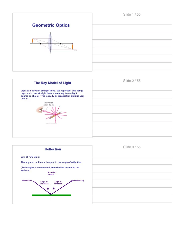
Law of reflection: The angle of incidence is equal to the angle of reflection. (Both angles are measured from the line normal to the surface.)

θi θr

Angle of incidence Angle of reflection Incident ray Reflected ray Normal to surface

Slide 3 / 55

slide-2
SLIDE 2

Reflection

When the light hits a rough surface and reflects, the law of reflection still holds but the angle of incidence varies so the light is diffused.

Slide 4 / 55 Reflection

With diffuse reflection, your eye sees reflected light at all angles but no image is really formed. With specular reflection (from a mirror) , your eye must be in the correct position.

Slide 5 / 55 Reflection

When you look into a plane (or flat) mirror, you see an image which appears to be behind the mirror. This is called a virtual image since the light does not go through it. The distance from the object to the mirror is the same as the distance from the mirror to the image.

Slide 6 / 55

slide-3
SLIDE 3

Spherical Mirror

Spherical Mirrors are shaped like sections of a sphere and may be reflective on either the inside (concave) or outside (convex).

Slide 7 / 55 Spherical Mirror

Rays coming in from a far away object are effectively parallel.

Slide 8 / 55 Spherical Mirror

For mirrors with large curvatures, parallel rays do not all converge at exactly the same point. This is called spherical aberration.

Slide 9 / 55

slide-4
SLIDE 4

Spherical Mirror

If the curvature is small, the focus is much more precise. The focal point is where the rays converge. The focal length of a spherical mirror is half the radius of curvature.

Slide 10 / 55 Spherical Mirror

We can use ray diagrams to determine where the image will be when using a spherical mirror. We draw three principle rays:

  • 1. A ray that is first parallel to the axis and then, after

reflection, passes through the focal point.

  • 2. A ray that first passes through the focal point and then,

after reflection, is parallel to the axis.

  • 3. A ray perpendicular to the mirror and then reflects back
  • n itself.
  • 4. A ray that strikes the mirror at the principal axis (and a

certain angle) and reflects back (at the same angle).

Slide 11 / 55

C F

Spherical Mirror

  • 1. A ray that is first parallel to the axis and then, after

reflection, passes through the focal point.

Slide 12 / 55

slide-5
SLIDE 5

C F

Spherical Mirror

  • 2. A ray that first passes through the focal point and then,

after reflection, is parallel to the axis.

Slide 13 / 55

C F

  • 3. A ray perpendicular to the

mirror and then reflects back

  • n itself.

Spherical Mirror Slide 14 / 55

C F

  • 4. A ray that strikes the mirror

at the principal axis (and a certain angle) and reflects back (at the same angle).

Spherical Mirror

Really, only two rays are needed to see where the image is located, but it is sometimes good to draw more.

Slide 15 / 55

slide-6
SLIDE 6

C F We can derive an equation that relates the object distance, image distance, and focal length.

Spherical Mirror Slide 16 / 55

C F We can also derive an equation that relates the object distance, image distance, and magnification.

Spherical Mirror

The negative sign indicates that the image is inverted.

Slide 17 / 55

C F This object is between the center of curvature and the focal point. Its image is magnified, real, and inverted.

Spherical Mirror Slide 18 / 55

slide-7
SLIDE 7

C F If the object is past the center of curvature...

Spherical Mirror Slide 19 / 55

C F If the object is past the center of curvature... the image is de- magnified, real, and inverted.

Spherical Mirror Slide 20 / 55

C F If the object is inside the focal point...

Spherical Mirror Slide 21 / 55

slide-8
SLIDE 8

C F If the object is inside the focal point... the image is magnified, virtual and upright.

Spherical Mirror Slide 22 / 55

If the object is inside the focal point...

Spherical Mirror

C F

Slide 23 / 55

If the object is inside the focal point... the image is de- magnified, virtual and upright.

Spherical Mirror

C F

Slide 24 / 55

slide-9
SLIDE 9

Refraction and Snell's Law

As we saw in Electromagnetic Waves, light slows when

traveling through a

  • medium. The index of

refraction (n) of the medium is the ratio of the speed of light in vacuum to the speed of light in the medium:

Slide 25 / 55 Refraction and Snell's Law

Light also changes direction when it enters a new medium. This is called refraction. The angle of incidence is related to the angle of refraction.

Air (n1) Water (n2) Normal line

#1 #2

Reflected ray Incident ray Refracted ray Air (n2) Water (n1) Normal line

#2 #1

Reflected ray Incident ray Refracted ray

n1 sin#1 = n2 sin#2 Slide 26 / 55 Refraction and Snell's Law

When light passes from air to a different medium back to air the ray that enters the medium is parallel to the ray that exits the medium. Using geometry, we can find the liner displacement between the emerging ray and the incident ray, if we know the angle of the incident ray and the thickness of the other medium.

Air (n1) Glass (n2)

#1 #2 #1 #2

Incident ray Emerging ray Incident ray Linear displacement

Slide 27 / 55

slide-10
SLIDE 10

Refraction and Snell's Law

This is why object look weird if they are partially under water.

Slide 28 / 55 Refraction and Snell's Law

Light also changes direction when it enters a new medium. This is called refraction. The angle of incidence is related to the angle of refraction.

Air (n2) Water (n1) Normal line

#2 #1

Incident ray Refracted ray

Slide 29 / 55 Refraction and Snell's Law

When the angle of incidence is larger than the critical angle, no light escapes the medium. This is called total internal reflection.

Air (n2) Water (n1) Normal line

#C #1

Source

Slide 30 / 55

slide-11
SLIDE 11

Thin Lenses

A thin lens is a lens whose thickness is small compared to its radius of curvature. Lenses can be converging or diverging. Converging lenses are thicker in the center than at the edges. Diverging lenses are thicker at the edges than in the center.

Slide 31 / 55 Thin Lenses

Converging lenses bring parallel rays to a focus which is the focal point. Diverging lenses make parallel light diverge. The focal point is the point where the rays would converge if the rays were projected back.

Slide 32 / 55 Thin Lenses

The power of a lens is the inverse of its focal point. Lens power is measured in diopters, D. 1 D = 1 m-1

Slide 33 / 55

slide-12
SLIDE 12

Thin Lenses and Ray Tracing

Ray tracing can be used to find the location and size of the image created by thin lenses as well as mirrors. They have similar steps.

  • 1. The first ray enters parallel to the axis and exits

through the focal point.

  • 2. The next ray enters through the focal point and then

exits parallel to the axis.

  • 3. The next ray goes through the center of the lens and

is not deflected.

Slide 34 / 55 Thin Lenses and Ray Tracing

  • 1. The first ray enters

parallel to the axis and exits through the focal point.

F F C C

Slide 35 / 55 Thin Lenses and Ray Tracing

  • 2. The next ray enters

through the focal point and then exits parallel to the axis.

F F C C

Slide 36 / 55

slide-13
SLIDE 13

Thin Lenses and Ray Tracing

  • 3. The next ray goes

through the center

  • f the lens and

is not deflected.

F F C C

Slide 37 / 55 Thin Lenses and Ray Tracing

Again, we only need two rays to see where the image is. When the object is between the focal point and center of curvature of a converging lens, the image is magnified, real, and inverted.

F F C C

Slide 38 / 55 Thin Lenses and Ray Tracing

When the object is inside the focal point...

F F C C

Slide 39 / 55

slide-14
SLIDE 14

Thin Lenses and Ray Tracing

When the object is inside the focal point... The image is magnified, virtual, and upright.

F F C C

Note that when the rays do not converge on one side of the lens, they do on the other side.

Slide 40 / 55 Thin Lenses and Ray Tracing

When the object is outside center of curvature...

F F C C

Slide 41 / 55 Thin Lenses and Ray Tracing

When the object is outside center of curvature... The image is de-magnified, real, and inverted.

F F C C

Slide 42 / 55

slide-15
SLIDE 15

Thin Lenses and Ray Tracing

For a diverging lens, when the object is between the focal point and the center of curvature...

F F C C

Slide 43 / 55 Thin Lenses and Ray Tracing

For a diverging lens, when the object is between the focal point and the center of curvature... The image is de-magnified, virtual, and upright.

F F C C

Slide 44 / 55 Thin Lenses and Ray Tracing

For a diverging lens, when the object is between the focal point and the center of curvature...

F F C C

Slide 45 / 55

slide-16
SLIDE 16

Thin Lenses and Ray Tracing

For a diverging lens, when the object is between the focal point and the center of curvature... The image is de-magnified, virtual, and upright.

F F C C

Slide 46 / 55 Thin Lenses and Ray Tracing

For a diverging lens, when the object is past the center of curvature...

F F C C

Slide 47 / 55 Thin Lenses and Ray Tracing

For a diverging lens, when the object is past the center of curvature... The image is de-magnified, virtual, and upright.

F F C C

Slide 48 / 55

slide-17
SLIDE 17

1 Diverging lenses always produce images that are virtual, upright, and demagnified.

True False

Slide 49 / 55

The same equation that relates the object distance, image distance, and focal length for spherical mirrors, works for thin lenses.

Thin Lenses Slide 50 / 55

The same equation that relates the object distance, image distance, and magnification for mirrors, works for thin lenses.

Thin Lenses

It works for power as well. The power is positive if the lens is converging and negative if the lens is diverging.

Slide 51 / 55

slide-18
SLIDE 18

The focal length is positive for converging lenses and negative for diverging lenses. The object distance is positive when it is on the same side at the light entering the lens and negative when it is

  • n the opposite side. (It is usually positive.)

The image distance is positive when it is a real image and negative when it is a virtual image. The height of the image is positive when it is upright and negative when it is inverted.

Thin Lenses: Sign Conventions Slide 52 / 55 Thin Lenses and Ray Tracing

For a combination of lenses...

F F C C Lens A Lens B F F C

Slide 53 / 55 Thin Lenses and Ray Tracing

For a combination of lenses... The image from the first lens becomes the object for the next.

F F C C Lens A Lens B F F C

Slide 54 / 55

slide-19
SLIDE 19

Summary

Index of refraction: Focal length: Mirror/Lens Equation: Magnification: Snell's Law: n1 sin#1 = n2 sin#2

Slide 55 / 55