
SLIDE 1
New Reference Listening Room for Two-Channel and Multi-Channel - - PDF document
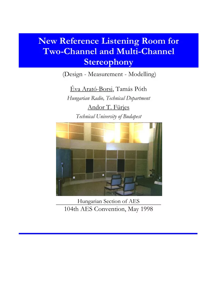
New Reference Listening Room for Two-Channel and Multi-Channel Stereophony (Design - Measurement - Modelling) va Arat-Borsi, Tams Pth Hungarian Radio, Technical Department Andor T. Frjes Technical University of Budapest Hungarian
104TH AES CONVENTION, MAY 1998
104TH AES CONVENTION, MAY 1998
The need…
The demand…
The design
The aim
104TH AES CONVENTION, MAY 1998
Basis of the design considerations
The room geometry
104TH AES CONVENTION, MAY 1998
The room dimensions: All dimensions suit the recommendation:
104TH AES CONVENTION, MAY 1998
The choice of the acoustical elements
104TH AES CONVENTION, MAY 1998
The sound field parameters specified by the EBU:
The measurements…
104TH AES CONVENTION, MAY 1998
104TH AES CONVENTION, MAY 1998
104TH AES CONVENTION, MAY 1998
THE MEASURED REVERBERATION TIME 0,1 0,2 0,3 0,4 0,5 0,6 10 12 5 16 20 25 31 5 40 50 63 80 1k 1,2 5k 1,6 k 2k 2,5 k 3,1 5k 4k 5k 6,3 k 8k f[Hz] T60[s] T 60 [s] EBU references
100 125 160 200 250 315 400 500 630 800 1k 1.25k 1.6k 2k 2.5k3.15k 4k 5k 6.3k 8k
104TH AES CONVENTION, MAY 1998
5 10 15 20 25 40 63 100 160 250 400 630 1k 1,6k 2,5k 4k 6,3k 10k 16k
f [Hz] A [dB]
FL FR FC
5 10 15 20 20 25 31, 5 40 50 63 80 100 125 160 200 250 315 400 500 630 800 1k 1,2 5k 1,6 k 2k 2,5 k 3,1 5k 4k 5k 6,3 k 8k 10k 12, 5k 16k 20k
f [Hz] A [dB]
SL SR
Left (SL) Right (SR)
Left (FL) Center (FC) Right (FR) 20 31.5 50 80 125 200 315 500 800 1.25k 2k 3.15k 5k 8k 12.5k 20k
104TH AES CONVENTION, MAY 1998
4 m 3.4 m 3.4 m 3.4 m 3.3 m 3.3 m
Left Center Right Left Right 4.6 m
Test procedures and equipment
104TH AES CONVENTION, MAY 1998
4 m 3.4 m 3.4 m 3.4 m 3.3 m 3.3 m
Left Center Right Left Right 4.6 m
Subjective results
104TH AES CONVENTION, MAY 1998
Subjective and objective parameters
10 2 1 10 2 2
s =
∞
2 2 max
t t 2 2 2
∞
104TH AES CONVENTION, MAY 1998
Why computer aided modelling?
Modelling with computers - review
104TH AES CONVENTION, MAY 1998
Modelling technical rooms - problems
Low Frequency Modelling (SYSNOISE)
104TH AES CONVENTION, MAY 1998
S
High Frequency Model
104TH AES CONVENTION, MAY 1998
Results of Modelling
Improvements
104TH AES CONVENTION, MAY 1998
104TH AES CONVENTION, MAY 1998
S
High Frequency Model
104TH AES CONVENTION, MAY 1998
Results of Modelling
Improvements