
SLIDE 1
Fog example
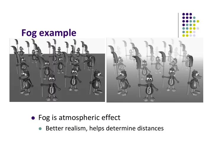
Fog is atmospheric effect
Better realism, helps determine distances
Fog example Fog is atmospheric effect Better realism, helps - - PowerPoint PPT Presentation
Fog example Fog is atmospheric effect Better realism, helps determine distances Fog Fog was part of OpenGL fixed function pipeline Programming fixed function fog Parameters: Choose fog color, fog model Enable: Turn it on
Better realism, helps determine distances
Parameters: Choose fog color, fog model Enable: Turn it on
start
End
P
float dist = abs(Position.z); Float fogFactor = (Fog.maxDist – dist)/ Fog.maxDist – Fog.minDist); fogFactor = clamp(fogFactor, 0.0, 1.0); vec3 shadeColor = ambient + diffuse + specular vec3 color = mix(Fog.color, shadeColor,fogFactor); FragColor = vec4(color, 1.0);
start end p end
s f p
Beer’s law: intensity of outgoing light diminishes
p f z
d
2
) (
p f z
d
P
8
Clouds Grass Terrain Skin
Image complexity does not affect the complexity
(transformation, clipping…)
Everthing is a texture except foreground characters that
Even details on foreground texture (e.g. clothes) is texture
Paste image (marble)
Simulate surface roughness (dimples)
Picture of sky/environment
S t 3D geometry 2D image 2D projection of 3D geometry
Procedural textures: E.g. fractal picture generated in .cpp file Textures applied in shaders
Bitmap texture:
s t (0,0) (1,1)
s t (x,y,z)
texture coordinates world coordinates
Read or generate image assign to texture (hardware) unit enable texturing (turn on)
OpenGL has texture objects (multiple objects possible)
First set up texture object
GLuint mytex[1]; glGenTextures(1, mytex); // Get texture identifier glBindTexture(GL_TEXTURE_2D, mytex[0]); // Form new texture object
Subsequent texture functions use this object Another call to glBindTexture with new name starts new
Define input picture to paste onto geometry Define texture image as array of texels in CPU memory
If uncompressed (e.g bitmap): read into array from disk If compressed (e.g. jpeg), use third party libraries (e.g. Qt, devil) to
bmp, jpeg, png, etc
Procedural texture: generate pattern in application code Enable texture mapping
glEnable(GL_TEXTURE_2D) OpenGL supports 1‐4 dimensional texture maps
target: type of texture, e.g. GL_TEXTURE_2D level: used for mipmapping (0: highest resolution. More later) components: elements per texel w, h: width and height of texels in pixels border: used for smoothing (discussed later) format,type: describe texels texels: pointer to texel array
1)
100 60 128 64 Remember to adjust target polygon corners – don’t want black texels in your final picture
Read or generate image assign to texture (hardware) unit enable texturing (turn on)
E.g. object (200,348,100) => (1,1) in image
(0,0) (1,0) (1,0) (1,1) (0,0,0) (200,348,100) s t
After specifying corners, interior (s,t) ranges also mapped Example? Corners mapped below, abc subrange also
s t
Example: Trying to map a picture to a quad For each quad corner (vertex), specify
May generate array of vertices + array of texture coordinates
points[i] = point3(2,4,6); tex_coord[i] = point2(0.0, 1.0);
x y z x y z x y z s t s t s t
Position 1 Tex3 Position 2
points array tex_coord array
Position 3 Tex0 Tex1
A c B C b a
void quad( int a, int b, int c, int d ) { quad_colors[Index] = colors[a]; // specify vertex color points[Index] = vertices[a]; // specify vertex position tex_coords[Index] = vec2( 0.0, 0.0 ); //specify corresponding texture corner index++; quad_colors[Index] = colors[b]; points[Index] = vertices[b]; tex_coords[Index] = vec2( 0.0, 1.0 ); Index++; // other vertices }
x y z x y z x y z s t s t s t
Position 1 Tex2 Position 2
points array tex_coord array
Position 3 Tex0 Tex1
a c b c b a
r g b r g b r g b
Color 1 Colors 2
colors array
Colors 3
a b c
Pass vertex, texture coordinate data as vertex array Set texture unit
GLuint vPosition = glGetAttribLocation( program, "vPosition" ); glEnableVertexAttribArray( vPosition ); glVertexAttribPointer( vPosition, 4, GL_FLOAT, GL_FALSE, 0,BUFFER_OFFSET(offset) );
GLuint vTexCoord = glGetAttribLocation( program, "vTexCoord" ); glEnableVertexAttribArray( vTexCoord ); glVertexAttribPointer( vTexCoord, 2,GL_FLOAT, GL_FALSE, 0, BUFFER_OFFSET(offset) );
// Set the value of the fragment shader texture sampler variable // ("texture") to the the appropriate texture unit. glUniform1i( glGetUniformLocation(program, "texture"), 0 );
Variable names in shader
in vec4 vPosition; //vertex position in object coordinates in vec4 vColor; //vertex color from application in vec2 vTexCoord; //texture coordinate from application
Vertex shader receives data, output texture coordinates to
texCoord = vTexCoord color = vColor gl_Position = modelview * projection * vPosition
in vec4 color; //color from rasterizer in vec2 texCoord; //texure coordinate from rasterizer uniform sampler2D texture; //texture object from application void main() { gl_FragColor = color * texture2D( texture, texCoord ); }
Textures applied in fragment shader Samplers return a texture color from a texture object
Lookup color of texCoord (s,t) in texture Original color
Output color Of fragment
(0,0) (1,0) (0,1) (1,1)
(s, t) interpolated based corners’ texture coordinates (why not just interpolate the color?)
coordinates are then used to perform texture lookup
Object geometry: geometry pipeline Image: pixel pipeline “complex” textures do not affect geometric complexity
geometry pipeline vertices pixel pipeline image Fragment processor
Read or generate image assign to texture (hardware) unit enable texturing (turn on)
still haven’t talked about setting texture parameters