SLIDE 1
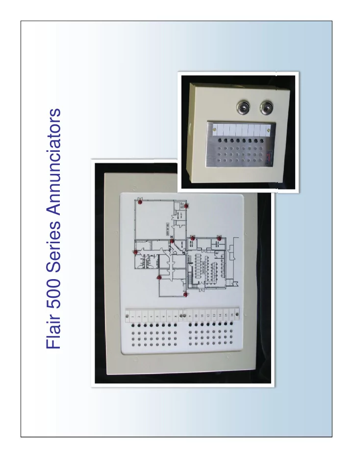
Flair 500 Series Annunciators
SLIDE 2 Annunciator Basics
Flair Multi-Zone Annunciators (MZAs) are fully functional, flexible, programmable micro controller based alarm control l Th b d i d d tl i j ti
- panels. They can be used independently or in conjunction
with other control panels and access control systems. T i l li i i l d l h h Typical applications include alarm systems where there are guards, officers, nurses or other personnel who need to monitor doors, rooms, objects or people quickly without
having to scroll through LCD screens or computers
- Micro Controller Based
- Highly Visible Display
- Single Touch Control
FEATURES Single Touch Control
SLIDE 3 User Interface
Typical 8 Zone Display The Basic 8 Zone Annunciator Module consists of 8 each, Yellow, Green, Red LEDs, and 8 Tactile Switches.
Yellow LED Indicates if the corresponding Zone is Bypassed. ON = Bypassed Green LED Indicates the Status of the Zone Input in Green LED Indicates the Status of the Zone Input in real-time. ON = Zone Secure OFF = Zone Faulted Flashing = Zone Trouble Red LED Indicates a Zone Alarm. Flashing = New Alarm Steady = Acknowledged Alarm Tactile Provides for Individual Zone Control Switch Acknowledge (Press Once) Reset (Press Once after Ack.) Bypass (Hold for 1 ½ seconds)
SLIDE 4 Inputs of the MZA
Back of MZA
Cont
Zone Inputs – Consist of eight Supervised Loop Inputs with one Common. Zone Inputs may be independently programmed for any one of five Input Types.
trol I n
y p yp N.C./N.O. N.C. N.O.
Zone I nputs
Fire High Security Control Inputs – Consist of four Digital
I ndividual Out
p g Control Inputs with one Common. Control Inputs may be independently programmed for any one of six Control Types
12 Vdc Serial Port
Acknowledge Reset Shunt Disable Shunt Disable w/ Memory
t
Shunt Disable w/ Memory Arm/Disarm Lamp Test
SLIDE 5
N.C./N.O - Zone Input Configuration
For use with N.C. and or N O contacts N.O. contacts. N.C/N.O. EOL Zones must have a 1000 Ohm resistor across them. If the Zone is Shorted or Open, it will Alarm, there is no Trouble condition no Trouble condition. Resistors should always be placed at the end of the wire run.
SLIDE 6
N.C. - Zone Input Configuration
For use with N.C. contacts. N.C. EOL Zones must have a 1000 Ohm resistor across them. An Open Zone will p generate an Alarm condition. A Shorted Zone will generate a Trouble condition.
SLIDE 7
N.O./Fire - Zone Input Configuration
For use with N.O. Contacts Contacts. N.O. EOL Zones must have a 1000 Ohm resistor across them. A Shorted Zone will generate an Alarm condition condition. An Open Zone will generate a Trouble condition.
SLIDE 8
High Security - Zone Input Configuration
High Security EOL Zones High Security EOL Zones monitor for 7 different Loop Resistance Ranges. Secure Loop = 2000 Ohms Alarm Loop = 5300 Ohms Magnetic Tamper = 1000 Ohms Loop Tamper = Short Open and Loop Tamper = Short, Open and ranges above and below the Secure Loop Resistance
SLIDE 9 Outputs of the MZA
Back of MZA
Cont
Individual Outputs – Consist of eight Open Collector Transistor Outputs, each with a maximum switch current of 100mA 24VDC. Individual Outputs may be programmed for any one of five Output Types
trol I n
any one of five Output Types Non-Latch Latched Pulsed
Zone I nputs
Timed Sounder Common Outputs – Consist of two Open Collector Transistor Outputs each with a
I ndividual Out
Collector Transistor Outputs, each with a maximum switch current of 100mA 24VDC, typically factory wired to an Audible Sounder and Common Relay Output. Common Outputs may be programmed for f i O t t T
12 Vdc Serial Port
any one of six Output Types Non-Latch Latched Pulsed
t
Pulsed Timed Sounder System Arm
SLIDE 10
Zone Output Configurations Zone Output Configurations
The 8 Individual Outputs act as a switch to ground and may be connected to a small audible device, LED lamp, low current relay w/ surge diode, input of a digital d i (PLC Di it l Di l Al P l PC) t device (PLC, Digital Dialer, Alarm Panel, or PC) etc… Non-Latch – Follows the Status of the Zone Input, automatically resetting hen the Zone Inp t is Sec re resetting when the Zone Input is Secure. Latched – Output will remain activated upon Alarm until the Zone Input is Secure and the Zone has been Acknowledged and Reset. p g Pulsed – Output will activate upon Alarm for a 3 Second Period, each time the Zone Input is Alarmed. Timed – Output will activate upon Alarm for a pre-programmed Time Period, then Automatically Reset. Sounder – Output will activate upon Alarm and remain on until the Zone has been Acknowledged.
SLIDE 11 Configuring the MZA Configuring the MZA
Characteristics of the Inputs and Outputs of each MZA and Outputs of each MZA Module are easily configured with the use of the Flair one page MZA Configuration g g software.
- Input Types
- Entry/Exit Delays
- Door Prop Delays
O T
- Output Types
- Output Mapping
SLIDE 12 Output Mapping Output Mapping
Input to Output Mapping Any Outputs may be configured to
- perate with any individual Input or
combination of Inputs. Connect Multiple Zones to a Single Output for control of:
- Digital Dialers
- Camera Switchers
- DVR’s
- Voice Annunciators
- Lighting
- Sirens
SLIDE 13 Communication Module
I CSP Port Operation Status LEDs Communication Status LEDs PC Serial Port 12 Vdc Output Relay Drivers Expansion Port y Link Port RS485 Port 1 RS485 Port 4 RS485 Port 3 RS485 Port 2
SLIDE 14 Communication Module Basics
The Communication Module (CM) is an accessory to the Annunciator that controls and routes RS485 Serial Communication between two or more Annunciator Cabinets Local/Remote – The CM can be used to connect a Local Annunciator Cabinet to one or more Remote Annunciator Cabinets, each with complete display and control of the Local Zones.
- Multiplex up to 512 Zones
- Micro Controller Based
FEATURES
c o Co t o e ased
- Easily Programmable
- Individual Status LEDs
SLIDE 15 RS485 Ports
- Each CM has four – RS485 Ports to connect up to four
Annunciator Cabinets in Local/Remote Configuration, with one g , Cabinet on each of the four RS485 Ports. L l C bi t t i ll h d i d t i th
- Local Cabinets are typically hard wired to sensors in the
surrounding building and display the status of those inputs. Remote Cabinets provide visual display and control of a Local C bi t t th l ti Cabinet at one or more other locations.
- Each RS485 Port can be configured as either Local or
Each RS485 Port can be configured as either Local or
- Remote. A Local Cabinet may be routed to several Remote
- Cabinets. A Remote Cabinet may only be routed to one Local
Cabinet Cabinet.
SLIDE 16 CM Link Port
- The CM Link Port can be used to connect two Communication
Modules together, in order to expand the number of Local/Remote Cabinets multiplexed to eight and/or to Link Local/Remote Cabinets over the Internet or a wireless transceiver.
PC Serial Port
- The PC Serial Port is used to Configure the CM using a
standard PC with an RS232 Serial Port.
SLIDE 17
Configuring the CM Configuring the CM
The Communication Module is easily configured with a standard PC, via the PC Serial Port, using the Flair one page CM Configuration Software Configuration Software. Configurable Features: Routing of Local Annunciator C bi t t R t Cabinet to one or more Remote Annunciator Cabinets. Output Expansion Port Features Virtual MZA CM Link Port Routing
SLIDE 18 Application Profiles
- Social Services Duress Alarm
- School/University Alarm
- Estate
- Upgrade/Retro-fit Existing Alarm Panel
- Access Control
SLIDE 19 Social Services Duress Alarm
503A-24 Local Annunciator Telecom Room 3rd Floor 500 CM COMMUNI CATI ON RS485 PORT 1 COMMUNI CATI ON MODULE 503A-24 Local Annunciator RS485 RS485 PORT 2 Telecom Room 2nd Floor 561R-72 Remote Annunciator Guard Station 1st Floor Lobby 503A-24 Local Annunciator Telecom Room 1st Floor
SLIDE 20 School/University Alarm
Lib l A t 503A-12 Local Annunciator 503A-12 Local A i t 503A-12 Local Annunciator T h l 503A-12 Local Annunciator Performing Arts Building Liberal Arts Building Mathematics/ Science Building Annunciator Annunciator Technology Building RS485 RS485 PORT 1
500 CM COMMUNI CATI ON MODULE
RS485 PORT 2 RS485 PORT 1 Local S 561BC-72 Local/ Remote Annunciator Sensors Door Window PI R Security Office Administration Building
SLIDE 21 Estate
Door 550A-48 Remote
Security
503A-48 Local Zone I nputs
PI R Sensors
Tele-Com
Remote Graphic Annunciator 500CM RS485 PORT 1 Local Annunciator RS485 PORT 2
Utility Room
550A-48 Remote
Office
500CM Communication Module RS485 PORT 3 RS485 PORT 4 Remote Graphic Annunciator 550A-48 Remote
Master Bedroom
Graphic Annunciator
SLIDE 22 Upgrade/Retro-fit Existing Alarm Panel
Existing Local Alarm Panel Existing Zone I nputs Existing Sensors Door Existing Field Wiring
Existing Alarm Panel
Panel p Window PI R g Remote Site 500CM Zone I nputs I ndividual Outputs Ethernet t CM Guard Station 1st Floor 500CM Communication Module RS485 PORT 1 550A-48 Local Graphic Annunciator to RS485 Converter C Link Port LAN 1st Floor Lobby 561BC-48 Remote Annunciator 500CM Communication M d l RS485 PORT 1 CM Link Port RS485 to Ethernet WAN Annunciator Module Port Converter
SLIDE 23 Access Control
Card Reader KeyPad Access Control Panel Door Sensor Door Control Remote Site 561BC-48 Remote Zone I nputs Guard Station 1st Floor Remote Annunciator 561R-48 Local Annunciator Lobby 500CM Communication Module RS485 PORT 1 500CM Communication Module RS485 PORT 1 CM Link Port CM Link Port RS485 Module Port Port
SLIDE 24 Simple Access Control
C d R d DPST Door Door Control Card Reader KeyPad Sensor Control Guard Station 1st Floor Lobby 561R-48 Local Zone I nputs y Annunciator