Fiber Optics Fundamentals Surasak Sanguanpong nguan@ku.ac.th - - PDF document

fiber optics fundamentals
SMART_READER_LITE
LIVE PREVIEW

Fiber Optics Fundamentals Surasak Sanguanpong nguan@ku.ac.th - - PDF document

1/15 Fiber Optics Fundamentals Surasak Sanguanpong nguan@ku.ac.th http://www.cpe.ku.ac.th/~nguan Last updated: 25 November 2004 Applied Network Research Group Department of Computer Engineering, Kasetsart


slide-1
SLIDE 1

Applied Network Research Group Department of Computer Engineering, Kasetsart University 1/15

Fiber Optics Fundamentals

Surasak Sanguanpong nguan@ku.ac.th http://www.cpe.ku.ac.th/~nguan

Last updated: 25 November 2004 Applied Network Research Group Department of Computer Engineering, Kasetsart University 2/15

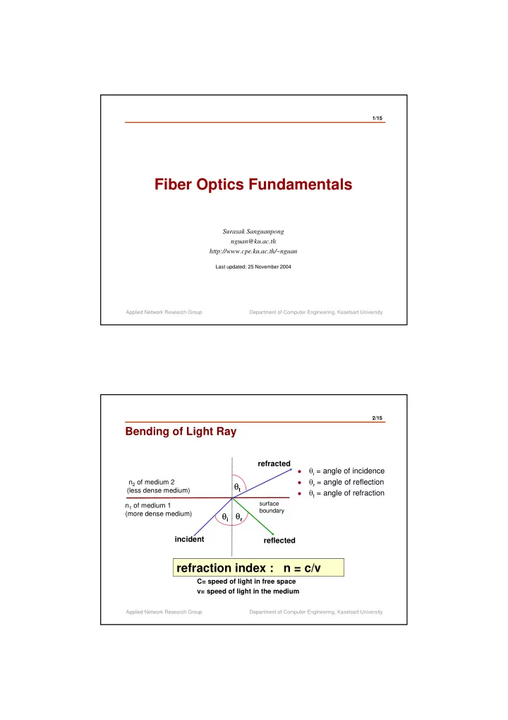
Bending of Light Ray

n2 of medium 2 (less dense medium) n1 of medium 1 (more dense medium)

θi

incident

θt

refracted

  • θi = angle of incidence
  • θr = angle of reflection
  • θt = angle of refraction

θr

reflected

surface boundary

refraction index : n = c/v

C= speed of light in free space v= speed of light in the medium

slide-2
SLIDE 2

Applied Network Research Group Department of Computer Engineering, Kasetsart University 3/15

Snell’s Law

1 1 2 2 3 3 4 4 n2 n1 n1>n2

θc = critical angle

θi θt n1sinθi = n2sinθt θi = sin-1n2/n1 = θc

critical angle

Applied Network Research Group Department of Computer Engineering, Kasetsart University 4/15

How it works

Loss Total reflection

core cladding

n2 n1

slide-3
SLIDE 3

Applied Network Research Group Department of Computer Engineering, Kasetsart University 5/15

Propagation Modes

πd λ M =

(n1)2-(n2)2 2

2

M = the number of modes d = core diameter (m) λ = wavelength (m)

n1 = refraction index of core n2 = refraction index of cladding

  • Finite number of angles at which the rays reflect and propagate
  • Each angle defines a path or a mode

Applied Network Research Group Department of Computer Engineering, Kasetsart University 6/15

Fiber classification

Single Mode Single Mode Multimode Multimode Step-Index Step-Index Fiber Optics Fiber Optics Graded-Index Graded-Index

slide-4
SLIDE 4

Applied Network Research Group Department of Computer Engineering, Kasetsart University 7/15

Multimode step-index

input signal

  • utput signal

core/cladding characteristics

n1 n2

Step-change

  • refraction index is uniformly throughout the core

Applied Network Research Group Department of Computer Engineering, Kasetsart University 8/15

Multimode graded-index

input signal

  • utput signal

core/cladding characteristics

n1 n2

Gradually change

  • Light begins to bend back toward the center,

eventually reflecting back

  • Because the material also less dense, the light

travels faster

slide-5
SLIDE 5

Applied Network Research Group Department of Computer Engineering, Kasetsart University 9/15

Single Mode

input signal

  • utput signal

core/cladding characteristics

n1 n2

  • Reducing the core diameter to that of a

single wavelength (3-10 micrometer) will let the light propagates along a one mode only

Applied Network Research Group Department of Computer Engineering, Kasetsart University 10/15

Typical Fiber Cable

cladding Jacket core

Single core Multicore

  • Materials for cladding and core:

glass cladding/glass core plastic cladding/glass core plastic cladding/plastic core

slide-6
SLIDE 6

Applied Network Research Group Department of Computer Engineering, Kasetsart University 11/15

Cable Structures Examples

core cladding fiber Color Coded Jacket Strength Elements Outer Jacket Central Strength Elements

Applied Network Research Group Department of Computer Engineering, Kasetsart University 12/15

Optical Fiber Comparison

Multimode Single mode Light source LED/ILD ILD Bandwidth >1 GHz/km up to 1000 GHz/km Wavelength 850, 1300 1300,1550 core/cladding 62.5/125* 8/125 Applications LAN, backbone Long distance, Telcom lines

* options with 50/125, 100/140

core cladding 8/125 micron 62.5/125 micron core cladding

slide-7
SLIDE 7

Applied Network Research Group Department of Computer Engineering, Kasetsart University 13/15

Loss in Glass Fibers

2.0 1.8 1.6 1.4 1.2 1.0 0.8 0.6 0.4 0.2 0.8 0.9 1.0 1.1 1.2 1.3 1.4 1.5 1.6 1.7 1.8

0.85μ band 1.30μ band 1.55μ band Wavelength (microns) Attenuation (dB/km)

Applied Network Research Group Department of Computer Engineering, Kasetsart University 14/15

Light Source

LED Injection Laser Diode

power wavelength

LED ILD

slide-8
SLIDE 8

Applied Network Research Group Department of Computer Engineering, Kasetsart University 15/15

Fiber in use

  • Plenums or non-plenums
  • plenum cable has a fire-resistant jacket, which will not burn,

smoke or

  • give off toxic fumes when expose to heat
  • Riser cables
  • cable that runs vertically; e.g. between floors in a building
  • Indoor or Outdoor
  • Indoor cable used in building. Outdoor cable used in

underground,

  • directed buries, and aerial applications between building.