feasibility study of shearing thickening fluid stf dampers
play

FEASIBILITY STUDY OF SHEARING THICKENING FLUID (STF) DAMPERS K. C. - PDF document

18 TH INTERNATIONAL CONFERENCE ON COMPOSITE MATERIALS FEASIBILITY STUDY OF SHEARING THICKENING FLUID (STF) DAMPERS K. C. Chang 1 , F. Y. Yeh 2, T. W. Chen 1 * 1 Department of Civil Engineering, National Taiwan University, Taipei, Taiwan (R.O.C.) 2


  1. 18 TH INTERNATIONAL CONFERENCE ON COMPOSITE MATERIALS FEASIBILITY STUDY OF SHEARING THICKENING FLUID (STF) DAMPERS K. C. Chang 1 , F. Y. Yeh 2, T. W. Chen 1 * 1 Department of Civil Engineering, National Taiwan University, Taipei, Taiwan (R.O.C.) 2 National Center for Research on Earthquake Engineering, Taipei, Taiwan (R.O.C.) * Corresponding author (d95521007@ntu.edu.tw) Keywords : shear thickening, damper, damping, viscous, hysteretic loop 
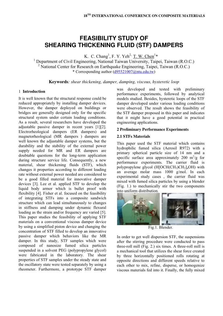
was developed and tested with preliminary 1 Introduction performance experiments, followed by analytical It is well known that the structural response could be models studied. Besides, hysteretic loops of the STF reduced appropriately by installing damper devices. damper developed under various loading conditions However, the damper deployed on buildings or were observed. The result shows the feasibility of bridges are generally designed only for the specific the STF damper proposed in this paper and indicates structural system under certain loading conditions. that it might have a good potential in practical As a result, several researchers have developed the engineering applications. adjustable passive damper in recent years [1][2]. 2 Preliminary Performance Experiments Electrorheological dampers (ER dampers) and magnetorheological (MR dampers ) dampers are 2.1 STFs Materials well known the adjustable damper systems, but the This paper used the STF material which contains durability and the stability of the external power hydrophilic fumed silica (Aerosil R972) with a supply needed for MR and ER dampers are primary spherical particle size of 14 nm and a doubtable questions for the long-term application specific surface area approximately 200 m 2 /g for during structure service life. Consequently, a new performance experiments. The carrier fluid is material, shear thickening fluids (STF), which polypropylene glycol (H[OCH(CH 3 )CH 2 ] n OH) with changes it properties according to different loading an average molar mass 1000 g/mol. In each rate without external power needed are considered to experimental study cases , the carrier fluid was be a good filled material for innovative damper mixed with fumed silica particles by using a blender devices [3]. Lee et al. applied STF to develop the (Fig. 1.) to mechanically stir the two components liquid body armor which is bullet proof with into uniform distribution. flexibility [4]. Fisher et al. focused on the feasibility of integrating STFs into a composite sandwich structure which can lead simultaneously to changes in stiffness and damping under dynamic flexural loading as the strain and/or frequency are varied [5]. This paper studies the feasibility of applying STF materials on a conventional viscous damper device by using a simplified piston device and changing the Fig.1. Blender. concentration of STF filled to develop an innovative passive damper which behaviors like the MR In order to get well dispersion STF, the suspensions damper. In this study, STF samples which were after the stirring procedure were conducted to pass composed of nanosize fumed silica particles three-roll mill (Fig. 2.) six times. A three-roll mill is suspended in a solvent PEG (polypropylene glycol) a mechanical tool that utilizes the shear force created were fabricated in the laboratory. The shear by three horizontally positioned rolls rotating at properties of STF samples under the steady state and opposite directions and different speeds relative to the oscillatory state were tested separately by using a each other to mix, refine, disperse, or homogenize rheometer. Furthermore, a prototype STF damper viscous materials fed into it. Finally, the fully mixed

  2. STFs were placed in a vacuum chamber to eliminate applied under steady state. It shows that the bubbles inside the STF. Regarding to the polypropylene glycol matrix is a Newtonian fluid concentrations of the STF conducted in this study whose viscosity keeps at constant value under are 7.5%, 10%, and 12.5 %w/w (Fig. 3.). different shear rate. Fig. 5 . Viscosity as a function of shear rate for PPG. Figure 6 shows the experimental result of the relationship between the dynamic viscosity and the shear rate of STF material applied under 10% Fig.2. Three-roll mill. concentrations. The results show that STF fluids have high nonlinear behavior, and perform from low to high amplitude strains at different shear angular frequencies of 20, 40, 60, 80 and 100 rad s -1 , respectively. The STF exhibits strain thickening at high strain amplitudes, with its complex viscosity showing an abrupt jump to higher levels at particular strains for different shear frequencies. The data in Figure 6 indicates that the transition to a strain- thickening behavior occurs at smaller strains as the Fig.3. STF materials. frequency of the deformation is increased. 2.2 Rheological Tests and Results As for rheological tests, rheological measurements were performed on a stress-controlled Rheometrics Scientific AR2000ex rheometer (Fig. 4a.). Fig.6. Dynamic strain sweeps at different angular frequencies for 10% ( w/w ). According to the experimental data, figure 7 gives Fig.4. (a) rheometer (b) cone and plate the response of the 10% ( w/w ) STF for a critical Varied dynamic frequency tests were conducted by shear strain γ c and the strain at the end of the using a 40 mm diameter cone-plate tool (Fig. 4b.) transition, γ m , as a function of ω . This figure could with a cone angle of 4 degree and a gap of 0.4 mm be used to predict whether the STF was in the low between the plate and the twitter. Figure 5 shows viscosity state, in the transition state or in the shear- the experimental result of relationship between the thickened state. viscosity and the shear rate of the carrier fluid

  3. the stabilized hysteresis loops. As can be seen from figure 10, the shape of the displacement damping force loop is strongly dependent on the loading frequency. For example, the peak damping force shows an increasing trend with frequency. In the low frequency range, such as 1 Hz, the STF presents a Newtonian fluid character. The area of the hysteretic loop per cycle denotes the energy dissipation capability. As the excitation frequency increases, the slope of the low velocity hysteresis loop increases. The damper works in the low viscosity state, in the Fig.7. γ c and γ m as a function of angular frequency. transition state and in the shear thickened state when the excitation frequency is at 3 and 5 Hz, respectively. The hysteresis loop changes 3 STF Damper Developed significantly as the excitation frequency passes 1 Hz. The mechanism of STF damper developed is similar Frequency Amplitude (mm) to a conventional single-tube damper which consists (Hz) 1 5 10 15 of a piston, one flow tunnel and a cylinder (Fig. 8.). 0.63 3.14 6.28 9.42 0.1 1.88 9.42 18.85 28.27 It consists 4 parts elements including cylinder, 0.3 3.14 15.71 31.42 47.12 0.5 piston head, oil seal and fluid. 6.28 31.42 62.83 94.25 1 18.85 94.25 188.50 282.74 3 31.42 157.08 314.16 471.24 5 62.83 314.16 628.32 942.48 10 Table1. Harmonic excitations test under different frequencies at fixed stoke. Fig.8. Drawing of STF damper developed. The photo of experimental layout of dynamic performance tests is shown in Figure 9. The STF damper was tested under harmonic excitations with (a) (b) different frequencies at fixed stoke. In this paper, the range of test frequencies is from 0.01Hz to 3 Hz according with the constant stroke of 1mm to 15mm (Table 1.). (c) (d) Fig.10. (a) 1mm stroke (b) 5mm stroke (c) 10mm stroke (d) 15mm stroke. Hysteretic loop of the 10% ( w/w ) STF damper. Fig.9. Layout of STF damper performance test. The experimental results in terms of damping force versus displacement at different frequencies are shown in figure 10. For each test, 6 cycles were repeated, and average values were taken to obtain 3

Download Presentation
Download Policy: The content available on the website is offered to you 'AS IS' for your personal information and use only. It cannot be commercialized, licensed, or distributed on other websites without prior consent from the author. To download a presentation, simply click this link. If you encounter any difficulties during the download process, it's possible that the publisher has removed the file from their server.

Recommend


More recommend