
SLIDE 1
Fabrication Method This PDE fabrication presentation is designed to - - PowerPoint PPT Presentation
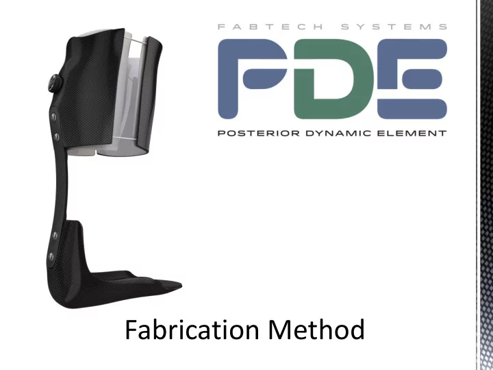
Fabrication Method This PDE fabrication presentation is designed to display elements of the fabrication processes with accompanying images to better visualize the fabrication process. Please make sure to refer to the PDE and BOA Closure
Using a 1/8” thick soft plastic interface material (Proflex™ with silicone) Pull the proximal posterior cuff. Be sure to make this section large enough to extend 1 ½” past midline join of anterior shell and posterior cuff. Label this piece with patient information and set aside for finishing.
Using a 1/8” thick semi dense soft foam (Black Puff) pull a seamless booty for the entire foot section. Label this piece with patient information and set aside for finishing.
Using 1/8” thick polypropylene pull the entire model using the same technique you would use for a standard plastic AFO. Ensure there are no wrinkles or excessive stretch within the trim lines. This will serve as both a spacer for the plastic and foam liners as well as a releasable surface to laminate on.
Keep the plastic join/seam as clean and straight across the shin section as possible. Trim away all excess plastic. Using grinding and buffing equipment smooth the plastic join/seam on the shin section focusing on the area within the trim lines.
The PDE spring is not symmetrical. The bend is closer to the distal end of the
Note: The PDE logo sticker on the face of the spring will be in the upright “readable” position.
For fitting and attachment to the model the spring is assembled as
proper final alignment and space for the lamination materials.
#1. Position the spring setup on the posterior of the model keeping it proximal enough of the heel to allow clearance in shoes ~3 ½” to 3 ¾”. #2. Once the position has been determined mark the model with two
edge of the cuff and the other to show the proximal edge of the foot plate.
Add the trim line mark up for cuff design. The Medial/lateral split for the proximal cuff should follow the coronal plane.
Proposed trim lines of the cuff system as well as the proposed routing pathways for the closure system.
Note: Keep Teflon™ tubing system away from proposed trim line edges by 1” if
Using a coarse sand paper abrade the Teflon™ ™ housing so it will stay secure in the laminate.
Note: This method displays the housing not using the supplied covered material tube braid.
The easiest way to do this is by folding the sand paper and pulling the Teflon™ ™ through.
Tape Teflon™ tubing into position.
Teflon™ should be long enough to reach the center of the dial system. Plug Teflon™ ends with clay.
With the Teflon™ tubing in position using masking tape. Use Composite 1 adhesive to liberally glue down the exposed Teflon™ .
Wipe excess adhesive off of the routed tubing. The masking tape is a great place to wipe all excess that isn’t needed.
Once the Composite1 adhesive has cured remove the masking tape. Use additional Composite1 adhesive and bond the open areas.
Wait 10 minutes for the adhesive to fully cure and bond to the Teflon™ tubing.
Using a blade or tip of a screwdriver carefully peel the cured tubing (complete) assembly off of the plastic and safely put aside for future placement.
Place the model on the table with the forefoot flat on the table. Using a square mark a vertical line for reference.
This reference mark is the ideal placement for the spring. In the event this mark is noticeably off center of the calf it is ok to alter it within a few degrees for aesthetics.
In a horizontal holder (vice) orient the model in a toe down position and set toe
Model in pipe holder with toe out set.
Fill both anchors with Composit1 adhesive.
Note: Hollowed machined cavities face model.
Place assembly on model in alignment.
The face of the spring should be level.
Fill any undercuts to minimize air issues during lamination.
Remove attachment screws from the PDE assembly leaving only the anchor plates bonded to model. Insert the set screws from the anchor kit into the anchor plate until they bottom out. Be sure the set screws are treated with a mold release of some type and after the installation the Allen wrench holes are filled with clay.
12K -/+ 45° Carbon Fiber Braid. 12K 0/90 Carbon Fiber Tape
Standard 12k weight 45° degree carbon tubular braid.
Fabtech CT6 12k weight 0/90 carbon tape.
Note: Fabtech CT6 12K carbon tapes are available in 10ft and 50ft sections.
and upper cuff. (See foot plate instructions as this is the final layer before
lamination)
Cover entire cuff section with 2ea 12k carbon braid oriented 45°
screws through the spaces in the
glued down with no wrinkles gaps
Note: All materials are run over the attachment plates. Keep materials even and flat on plate surfaces.
Add a layer of 0/90 carbon tape
Wrap 0/90 carbon tape around model to the midline. Trim any excess that goes past midline.
If the 0/90 carbon tape did not extend to midline, cut an extra piece of carbon tape and add so it extends to midline.
If using the BOA Closure System, add it now.
Make sure the Teflon™ tubing and routing all line up and are in the correct position that was established earlier. Adjust if needed.
Add a the second layer of 0/90 carbon tape and trim at midline
Form 12K 0/90 carbon tape
Make sure it “locks” the system in well, as this will help hold it in position when laminating with resin.
Add the plastic tooling spacers. Note: Make sure lamination screws are exposed from underneath carbon materials.
Lamination set screws should look like this.
Cover the proximal cuff in the final layer of 12K Carbon braid.
and upper cuff.
This presentation is our recommended minimum Lay-up schedule. More material may be needed for heavy or highly active users.
Cover the footplate in 2ea layers 12K carbon braid at 45° degree orientation.
Trim off excess material.
Cover footplate with 3ea layers CT6 12K carbon tape in 0/90 orientation.
Cut fabric to contour around footplate.
Keep fiber orientation straight.
Note: This is the minimum reinforcement at three layers. four layers are common with higher activity
After all CT6- 12K 0/90 carbon tape layers have been added cover with 1ea layer of 12K carbon braid at 45° degrees.
Place the lamination dummies on the model with the exposed set screws to hold it in position.
Cover the entire model in a final layer of 12K carbon fiber braid at 45° degrees.
Note: This is the last layer of 12K Carbon braid. Both the upper cuff and foot plate should have a total of 4ea layers now.
Split the final layer open by the ankle to get the fabric to lay down nicely.
Use tape or spray glue to secure loose ends.
Laminate with a minimum of 500grams of Epoxy resin. PN:RES1.
Note: Epoxy resin is recommended for durability.
https://www.youtube.com/watch?v=70y_UYVebvw https://www.clickmedical.co/resources/video-gallery
Additional Boa closure information can be found at the web addresses below.