Estimation of Gain Factors for the Cold Neutron Source in European - - PDF document

estimation of gain factors for the cold neutron source in
SMART_READER_LITE
LIVE PREVIEW

Estimation of Gain Factors for the Cold Neutron Source in European - - PDF document

Transactions of the Korean Nuclear Society Virtual Spring Meeting July 9-10, 2020 Estimation of Gain Factors for the Cold Neutron Source in European Research Reactor Han Jong Yoo*, Kyung-O Kim, Byungchul Lee, and Gyuhong Roh Korea Atomic Energy


slide-1
SLIDE 1

Estimation of Gain Factors for the Cold Neutron Source in European Research Reactor

Han Jong Yoo*, Kyung-O Kim, Byungchul Lee, and Gyuhong Roh Korea Atomic Energy Research Institute, 1045 Daedeok-daero, Yuseong-gu, Daejeon, Korea *Corresponding Author: hjyoo@kaeri.re.kr

  • 1. Introduction

From a couple of decades ago, the analysis on micro- structures with characteristic lengths of ~100 Å has been become important for both science and technology [1]. Especially, the neutrons with low energy (E < 5 meV) are well matched with the characteristic dimensions of the micro-structures. In order to obtain the neutrons with energy less than 5 meV, a Cold Neutron Source (CNS) should be used to slow-down the fission neutrons, and the principal design criteria of the CNS is a significant increase of cold neutrons at the experimental beam tube. Research reactor design division in KAERI designed a CNS facility for the research reactor in Europe, which is performed on the basis of the experience with cold neutron source system of HANARO. Performance of this facility is decided by comparing the strength of the cold neutron current that enters to the neutron beam guide when the cooling system is on and off, called as gain

  • factor. In this research, gain factor of the designed system

is evaluated using 3-D Monte Carlo code (MCNP6).

  • 2. Cold Neutron Source

Cold neutrons are obtained by shifting the neutron spectrum through moderating thermal neutrons further using liquid hydrogen at 20K. 2.1. Liquid Hydrogen Liquid hydrogen is a key factor of cold neutron source

  • quality. To maintain hydrogen in liquid state, sufficient

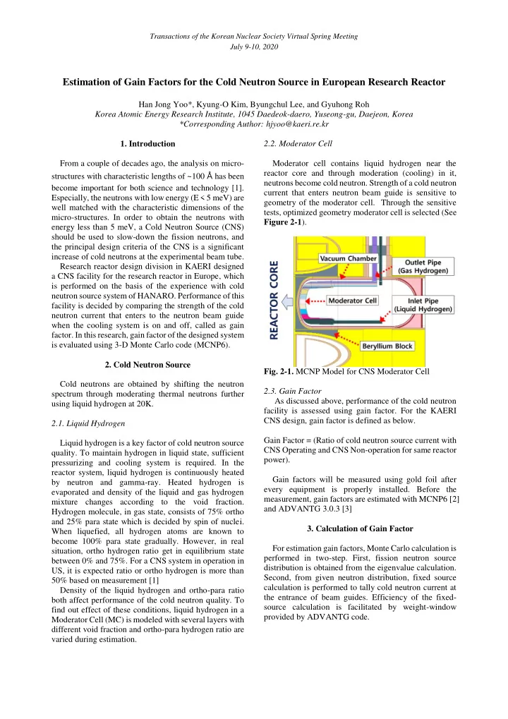
pressurizing and cooling system is required. In the reactor system, liquid hydrogen is continuously heated by neutron and gamma-ray. Heated hydrogen is evaporated and density of the liquid and gas hydrogen mixture changes according to the void fraction. Hydrogen molecule, in gas state, consists of 75% ortho and 25% para state which is decided by spin of nuclei. When liquefied, all hydrogen atoms are known to become 100% para state gradually. However, in real situation, ortho hydrogen ratio get in equilibrium state between 0% and 75%. For a CNS system in operation in US, it is expected ratio or ortho hydrogen is more than 50% based on measurement [1] Density of the liquid hydrogen and ortho-para ratio both affect performance of the cold neutron quality. To find out effect of these conditions, liquid hydrogen in a Moderator Cell (MC) is modeled with several layers with different void fraction and ortho-para hydrogen ratio are varied during estimation. 2.2. Moderator Cell Moderator cell contains liquid hydrogen near the reactor core and through moderation (cooling) in it, neutrons become cold neutron. Strength of a cold neutron current that enters neutron beam guide is sensitive to geometry of the moderator cell. Through the sensitive tests, optimized geometry moderator cell is selected (See Figure 2-1).

  • Fig. 2-1. MCNP Model for CNS Moderator Cell

2.3. Gain Factor As discussed above, performance of the cold neutron facility is assessed using gain factor. For the KAERI CNS design, gain factor is defined as below. Gain Factor = (Ratio of cold neutron source current with CNS Operating and CNS Non-operation for same reactor power). Gain factors will be measured using gold foil after every equipment is properly installed. Before the measurement, gain factors are estimated with MCNP6 [2] and ADVANTG 3.0.3 [3]

  • 3. Calculation of Gain Factor

For estimation gain factors, Monte Carlo calculation is performed in two-step. First, fission neutron source distribution is obtained from the eigenvalue calculation. Second, from given neutron distribution, fixed source calculation is performed to tally cold neutron current at the entrance of beam guides. Efficiency of the fixed- source calculation is facilitated by weight-window provided by ADVANTG code.

Transactions of the Korean Nuclear Society Virtual Spring Meeting July 9-10, 2020

slide-2
SLIDE 2

3.1. Neutron Source for Fixed Source Calculation European research reactor core is configured on a 6 ⅹ 7 positions grid plate (see Figure 3-1). Standard core consists of 16 standard fuel elements and 4 control

  • elements. The fuel is Low Enriched Uranium (LEU)

Uranium Silicide (U3Si2). 22 Beryllium reflectors are surrounding fuel elements and other slots are reserved for irradiation.

  • Fig. 3-1. Standard Core and Position Index

The eigenvalue calculation is first performed to obtain neutron source distribution for fixed source calculation. In the calculation, the fuel elements are axially segmented into 15 mesh cells, and the fission neutrons emitted from each mesh are obtained by F4 tally. Figure 3-2 shows the relative fission neutron distribution produced from each fuel element. As shown in the figure, the standard element positioned at the core center (D3, C3, E4, and D5) produce more fission neutrons than

  • thers, and much less fission neutron are produced from

the control elements (C3, E3, C5, and E5) which are divided into upper and lower fuel regions (Position Index: see Figure 3-1). These results are finally taken as the neutron source distribution to estimate the gain factor for cold neutron source.

  • Fig. 3-2. Relative Axial Fission Neutron Distribution in

Each Fuel Assembly 3.2. Neutron Current at the Entrance of Beam Guides Some of cold neutrons came out of CNS MC may reach entrance of neutron beam guide. Neutrons whose path make a small angle with the axis of the beam tube less than 1º for a neutron wavelength of 5Å or 2º for 10Å can enter mirror guide system. During MCNP calculation,

  • nly neutrons of wavelength of 5Å and 10Å are tallied at

the entrance of beam guides within acceptance angle. Only few of neutrons may reach the entrance of the beam guide. To get reliable calculation results, sufficient number (2.0E+8) of neutrons are simulated and to improve the efficiency of calculation, variance reduction techniques are used.

  • 4. Calculation Results

Table 4-1 shows the gain factors as a function ortho- para ratio for each guide. The ratio of ortho hydrogen changed from 35% to 75%. For the neutrons of 10Å, gain factors are higher than 26 in any condition and the maximum is 36.6. Relatively smaller gain factors occur for the case of 65% ortho hydrogen while similar gain factors are obtained for other ortho content cases. Neutron beam guide 2 and 3 shows relatively higher gain

  • factors. For the neutrons around 5Å, gain factors are

proportional to the ortho hydrogen ratio and the lowest value occurs at 35% ortho hydrogen. The gain factors lay between 14 and 15 except 65% and 35% ortho hydrogen cases but it is smaller for 65% ortho hydrogen again as for 10Å neutron. Table 4-1. Gain Factors for Each Guide

Ortho:Para Ratio Guide # 10Å 5Å Gain Factor Gain Factor 75:25 1 28.41 14.57 2 35.67 14.53 3 32.73 15.50 4 27.57 14.60 65:35 1 26.65 13.83 2 34.03 13.65 3 30.91 14.45 4 26.25 13.97 55:45 1 27.83 14.26 2 36.60 13.98 3 32.91 14.97 4 28.07 14.38 45:55 1 28.75 14.15 2 36.61 14.18 3 33.37 14.73 4 27.21 14.10 35:65 1 27.78 12.75 2 35.80 12.62 3 31.95 14.20 4 27.67 13.74

In general, higher cold neutron flux is expected with higher ortho hydrogen content because of larger neutron

Transactions of the Korean Nuclear Society Virtual Spring Meeting July 9-10, 2020

slide-3
SLIDE 3

scattering cross section. It is clearly shown in the Figure 4-1 [1] and over 40% of ortho hydrogen content, cold neutron flux is almost saturated. Calculation results in Table 4-1 shows similar trend but it seems gain factor is smaller than others at 65:35 of ortho-para ratio. It is expected that it comes from statistical error of Monte Carlo calculation although the error is suppressed to be less than 5%.

  • Fig. 4-1. Relative Brightness (0~5meV) vs. Para LH2

Fraction (10% voids, 20mm thick annulus moderator cell)

  • 5. Conclusion

Gain factor for a CNS facility of European research reactor is calculated by fixed source calculation with MCNP6 and ADVANTG codes. CNS MC is modeled in detail by considering void ratio and ortho-para ratio of liquid hydrogen. With ortho hydrogen ratio higher than 40%, gain factors are 14~15 for 5Å and 26~36 for 10Å for each guide. Proportionality between ortho hydrogen ratio and gain factor is not strong for ortho content higher than 40%. It is expected that ratio of the ortho hydrogen would be higher than 50% in operating condition. During

  • peration, some conditions such as a pressure of the

liquid hydrogen can be adjusted to find out optimum

  • peration condition.

ACKNOWLEDGEMENTS This work has been conducted as a part of the Development of Research Reactor Technology project sponsored by Ministry of Science and ICT of Korean goverment. REFERENCES

[1] P. Kopetka, and et al., NIST Liquid Hydrogen Cold Source, NISTIR 7352, National Institute of Standards and Technology, 2006. [2] D.B. Pelowitz (ED.), and et al., MCNP6TM User’s Manual Version 1.0, LA-CP-13-00634, Rev. 0, LANL, 2013. [3] S.W. Mosher, and et al., ADVANTG-Automated Variance Reduction Parameter Generator, ORNL/TM-2013/416, Rev. 1, ORNL, 2015. Transactions of the Korean Nuclear Society Virtual Spring Meeting July 9-10, 2020