EFFECT OF PROCESS CONDITIONS ON POROSITY IN OUT-OF-AUTOCLAVE PREPREG - - PDF document

effect of process conditions on porosity in out of
SMART_READER_LITE
LIVE PREVIEW

EFFECT OF PROCESS CONDITIONS ON POROSITY IN OUT-OF-AUTOCLAVE PREPREG - - PDF document

18 TH INTERNATIONAL CONFERENCE ON COMPOSITE MATERIALS EFFECT OF PROCESS CONDITIONS ON POROSITY IN OUT-OF-AUTOCLAVE PREPREG LAMINATES J. Kay, L. Fahrang, K. Hsiao, G. Fernlund* Department of Materials Engineering, The University of British


slide-1
SLIDE 1

18TH INTERNATIONAL CONFERENCE ON COMPOSITE MATERIALS

1 Introduction Out-of-autoclave (OOA) prepregs are designed to be vacuum-bag-only (VBO) processed and cured in an

  • ven. One major difference between OOA prepregs

and autoclave prepregs is that the latter relies on a combination of vacuum and high applied pressure to suppress porosity originating from entrapped gases and volatiles in the laminate. The absence of an autoclave limits the compaction pressure to 1 atm, which is a challenge in OOA processing [1]. In OOA processing, entrapped gases and volatiles within the laminate cannot be dissolved into solution under the low compaction pressure. Consequently, void free laminates are achieved by removing entrapped gas and volatiles by vacuum through engineered gas extraction pathways in the prepreg (Figure 1) [2]. One key design feature of OOA prepregs is their ability to transport gases and volatiles; a secondary design feature is to limit the amount of off-gassing during the resin curing reaction [3]. The presence of voids and porosity are a concern when processing composite materials, as voids in the final cured laminate are detrimental to mechanical

  • performance. Voids are here defined as empty, or air

filled, cavities in the laminate whereas porosity is defined as the volume fraction of voids in the

  • laminate. The formation and growth of voids is

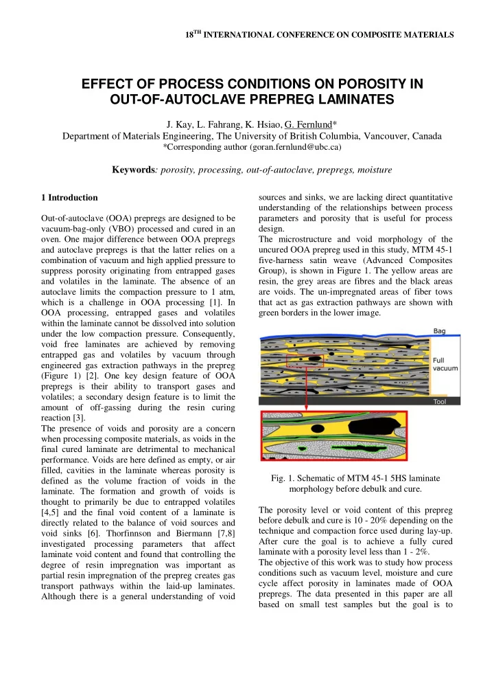
thought to primarily be due to entrapped volatiles [4,5] and the final void content of a laminate is directly related to the balance of void sources and void sinks [6]. Thorfinnson and Biermann [7,8] investigated processing parameters that affect laminate void content and found that controlling the degree of resin impregnation was important as partial resin impregnation of the prepreg creates gas transport pathways within the laid-up laminates. Although there is a general understanding of void sources and sinks, we are lacking direct quantitative understanding of the relationships between process parameters and porosity that is useful for process design. The microstructure and void morphology of the uncured OOA prepreg used in this study, MTM 45-1 five-harness satin weave (Advanced Composites Group), is shown in Figure 1. The yellow areas are resin, the grey areas are fibres and the black areas are voids. The un-impregnated areas of fiber tows that act as gas extraction pathways are shown with green borders in the lower image.

  • Fig. 1. Schematic of MTM 45-1 5HS laminate

morphology before debulk and cure. The porosity level or void content of this prepreg before debulk and cure is 10 - 20% depending on the technique and compaction force used during lay-up. After cure the goal is to achieve a fully cured laminate with a porosity level less than 1 - 2%. The objective of this work was to study how process conditions such as vacuum level, moisture and cure cycle affect porosity in laminates made of OOA

  • prepregs. The data presented in this paper are all

based on small test samples but the goal is to

EFFECT OF PROCESS CONDITIONS ON POROSITY IN OUT-OF-AUTOCLAVE PREPREG LAMINATES

  • J. Kay, L. Fahrang, K. Hsiao, G. Fernlund*

Department of Materials Engineering, The University of British Columbia, Vancouver, Canada

*Corresponding author (goran.fernlund@ubc.ca)

Keywords: porosity, processing, out-of-autoclave, prepregs, moisture

slide-2
SLIDE 2

translate these results into better understanding of how to process large and complex laminates with low porosity levels. 2 Methods Laminates with different sizes and thicknesses were laid up and cured according to the prepreg manufacturer’s specifications. In the first study, where the objective was to evaluate how porosity evolves during the cure cycle, the cure cycle was interrupted at different times in the cycle and laminates cooled down and evaluated for porosity using optical microscopy and image analysis. Optical microscopy samples were prepared based on ASTM E2015-04 “Standard guide for preparation of plastic and polymeric specimens for micro-structural examinations” [9]. Preparation of partially cured samples is difficult as the epoxy matrix is still soft. Therefore, cutting, grinding and polishing of these samples can result in resin smearing, fibre pull-out

  • r fibre breakage and special care must be taken

during the preparation of these samples. In order to minimize the surface damage, samples were mounted with a special mounting resin, Epo-color (Buehler Co.). This low viscosity, dye enhanced mounting resin is designed to identify and highlight pores and cracks which are difficult to distinguish from the base material. This material appears bright red under dark-field or polarized light illumination (Figure 2). The mounted samples were ground, polished and mosaic images were taken from the entire cross section.

  • Fig. 2: Epo-color resin under a) bright-field and b)

dark-field illumination. Image analysis was performed to measure the area fraction of the voids. The typical void morphology

  • f studied samples is shown in Figure 3.
  • Fig. 3: Different types of voids.

As shown in Figure 3, there is a relatively complex void morphology with a wide range of shapes, sizes and locations. The voids were categorized into three groups based on their morphology and location. The first group are “inter-laminar voids”, which are located between the lamina and have an elongated

  • shape. Both location and shape of these voids

suggest that their origin is entrapped air during lay

  • up. The second group is “resin voids” which are

surrounded with resin and have a circular shape. Off-gassing from resin moisture or other volatiles generated during prepregging in the system can form resin void. The last group are “fibre tow voids” that are located inside the fibre tows. Fibre tow voids are inter-connected and continuous vacant spaces inside the un-impregnated region of the fibre tows. The area fraction of each type of voids is measured individually and their sum is reported as the total volume fraction of voids, or void content. XT = XI + XF + XR (1) Where XT [vol%]: Total void content, XI [vol%]: Interlaminar void content, XF [vol%]: Fiber tow void content, XR [vol%]: Resin void content. The “ImageJ” software was used for image analysis and to determine the volume fraction of voids in the samples. The cure cycle used in the first study was a ramp at 0.5 °C/min and hold at 80 °C for 22 hours followed by a post cure at 180°C. The cure cycle was interrupted, and samples removed for microscopy, at 0, 2, 4, 6 and 8 hours into the cure cycle. The relative humidity of the laminate prior to cure was 35 – 50% and the vacuum level during cure 100%. The laminates were 8 ply thick with a [0]8 lay-up and the laminate size was 127 by 127 mm.

slide-3
SLIDE 3

EFFECT OF PROCESS CONDITIONS ON POROSITY IN OUT-OF-AUTOCLAVE PREPREG LAMINATES

In the second study the effect of vacuum level and moisture on final laminate porosity was evaluated. Small, 25.4 mm by 25.4 mm, four ply samples with a [0]4 lay-up made of MTM 45-1 five harness satin weave (Advanced Composites Group) were moisture conditioned in a humidity chamber (Figure 4) prior to cure at 120°C for four hours under different vacuum levels.

  • Fig. 4: Humidity chamber.

Four different laminate humidity levels were achieved by filling the humidity chamber with a desiccant (<5% humidity), ambient air (35-50% humidity), salt solution (75% humidity) and water (100% humidity), and letting the laminate sit four five days in the humidity chamber to reach full

  • saturation. The weight gain of the laminates were

measured as a function of time with a laboratory scale to ensure that steady-state conditions were reached prior to cure, and to measure the mass of water absorbed by the different laminates. After humidity conditioning the samples were quickly placed inside a pre-made vacuum bag and immediately cured under different vacuum levels. Vacuum was applied at the beginning of the heat-up ramp and no room temperature debulking was

  • performed. Samples were cured under four different

humidity levels (<5%, 35-50%, 75%, 100%) and three different vacuum levels (60%, 80%, 100%). The vacuum level was controlled with a vacuum

  • regulator. After cure the samples were sectioned,

polished, and images of the cross-sections were taken using an optical microscope. Image analysis was then used to quantify the porosity levels in the samples as described earlier. 3 Results Figure 5 shows the evolution of different types of voids during the cure cycle for the first test. The cure cycle was a ramp at 0.5 °C/min and hold at 80 °C for 22 hours follow by a post cure at 180 °C.

5 10 15 20 25 30 2 4 6 8 10 12 14 16 18 20 22 24 26 28 30 Time (hr) Void content (%)

  • 150
  • 130
  • 110
  • 90
  • 70
  • 50
  • 30
  • 10

10 30 50 70 90 110 130 150 170 190 Temperature (°C) XT XI XF XR Cure cycle 5 10 15 20 25 30 2 4 6 8 10

Time (hr) Void content (%)

  • 40
  • 20

20 40 60 80

Temperature (°C)

XT XI XF XR Cure cycle

  • Fig. 5. Top: Evolution of voids in a 127 by 127 mm

8 ply MTM 45-1 5HS laminate; Bottom: enlargement view of top graph [10]. Figure 5 shows that the total void content decreases continuously during the cure cycle. The void content started at 11.8 %, decreased to 2.81 % in two hours and reached a plateau (0.065%) after four hours. Although, the resin gels after approximately 18.5 hours using this cure cycle, the void morphology is constant after four hours. The figure also shows the evolution of the different types of voids during the cure cycle. The amount of inter-laminar voids is the greatest, while the amounts of fibre tow voids and resin voids are smaller. Both inter-laminar and fibre tow voids decrease with time, whereas resin voids are approximately constant through the process. Inter-laminar voids start at 9.25%, fall sharply to 2.5% in two hours and reach a plateau after four

  • hours. Fibre tow voids are about 2.5% at the

beginning, decrease to 0.26% after two hours and are approximately zero after four hours. Resin voids

Laminate Rack Liquid or Desiccant

slide-4
SLIDE 4
  • nly give a small contribution to the total void

content and are almost constant (~ 0.03%) during the cure cycle [10]. The final void morphology, at the end of the cure cycle, is shown in Figure 6, demonstrating a very low void content.

  • Fig. 6. Micrograph of a fully cured laminate cross-

section: 35 - 50% humidity & 100% vacuum. The second study examined the effect of vacuum level and humidity on the final porosity of cured

  • laminates. The effect of vacuum and humidity levels
  • n porosity is shown in the following graphs and
  • micrographs. Figure 7 (top) shows a micrograph of a

sample cured at 0.1% humidity and 100% vacuum, giving a porosity free laminate. The bottom image shows a sample cured at 100% humidity and 60% vacuum, resulting in significant porosity both within the fibre tows as well as outside the tows. Figures 8 and 9 show the measured tow and interlaminar and resin voids for laminates cured at different humidity and vacuum levels. As expected, the amount of tow voids increases as the level of vacuum decreases and humidity increases. Interlaminar and resin voids follow the same trend except for the sample with 60% vacuum level and 75% of relative humidity, which may be an outlier. Reducing the vacuum level lowers the gas extraction driving force, which result in higher void contents. Increasing the relative humidity also increases porosity by increasing the amount of water vaporization. This second study showed that the effect of poor vacuum and high humidity have a relatively small effect on porosity. What is important in this secibd study is that the sample size is very small (25.4 by 25.4 mm), which means that the applied vacuum readily can extract trapped air and water vapour from the whole laminate very quickly. In larger laminates, the time scale of gas transport is much greater, often of the order of hours [6], which means that trapped air and water vapourized due to low gas pressure often cannot escape the laminate resulting in much higher porosity levels than seen in the small laminates in this study.

  • Fig. 7. Micrograph of laminate cross-sections. Top:

0.1% humidity & 100% vacuum; Bottom: 100% humidity & 60% vacuum.

  • Fig. 8. Measured volume fraction of voids in the

fibre tows at different humidity and vacuum levels.

slide-5
SLIDE 5

EFFECT OF PROCESS CONDITIONS ON POROSITY IN OUT-OF-AUTOCLAVE PREPREG LAMINATES

  • Fig. 9. Measured volume fraction of interlaminar

and resin voids at different humidity and vacuum levels. 4 Conclusions

  • In a 80°C cure cycle, a void free (<1%)

laminate is achieved long before gellation (≈ 4 hrs).

  • Total void content, interlaminar voids, and

voids within fiber tows decrease during the cure cycle. Resin voids only give a small contribution to the total void content and are almost constant (~ 0.03%) throughout the cure cycle.

  • Increasing the level of humidity and

decreasing the level of vacuum results in higher void contents.

  • The measured porosity is very low (<4%)

for small samples (25.4 by 25.4 mm), given the high humidity and poor vacuum applied. Further experiments are being performed to evaluate how these results scale with specimen size, time under vacuum, and measurements of gas transport in the laminates.

  • 5. References

[1] S. S. Tavares, V. Michaud, J.-A. E. Månson “Assessment

  • f

semi-impregnated fabrics in honeycomb sandwich structures”. Composites Part A

  • Vol. 41, 1, pp 8-15, 2010.

[2] C. Ridgard “Next Generation Out of Autoclave”. SAMPE 2010 Seattle, WA, May 17-20, 2010. [3] S. Thomas, S. R. Nutt “Temperature Dependence of Resin Flow in a Resin Film Infusion (RFI) Process by Ultrasound Imaging”. Applied Composite Materials, 16, 138-196, 2009. [4] A. R. Mallow, F. C. Campbell “Autoclave Processing”. In R. S. Davé & A. C. Loos (Eds.), Processing of Composites (pp. 501). Cincinnati, USA: Hanser/Gardner Publications, Inc., 2000. [5] G. F. Xu, L. Repecka, S. Mortimer, S. Peake, J. Boyd “Manufacture of Void-Free Laminates and Use Thereof (pp. 22). United States: Cytec Technology

  • Corp. 2002.

[6] A. R. A. Arafath, G. Fernlund, A. Poursartip, “Gas Transport in Prepregs: Model and Permeability Experiments”. ICCM-17, Edinburgh Scotland, Jul 27- 31, 2009. [7] B. Thorfinnson, T. F. Biermann “Production of Void Free Composite Parts Without Debulking”. 31st International SAMPE Symposium, Las Vegas, Nevada, April 7-10, 1986. [8] B. Thorfinnson, T. F. Biermann “Degree of Impregnation of Prepregs - Effects on Porosity”. 32nd International SAMPE Symposium, Anaheim, California, April 6-9, 1987. [9] E2015-04, “Standard Guide for Preparation of Plastics and Polymeric Specimens for Microstructural Examination”, ASTM International, West Conshohocken, PA., 2004. [10] L. Farhang, G. Fernlund, “Void Evolution and Gas Transport During Cure in Out-of-Autoclave Prepreg Laminates”. SAMPE 2011 Long Beach, CA, May 23- 26, 2011.