EE182 Computer Organization and Design Winter 1998 Chapter 5 - - PDF document

ee182 computer organization and design winter 1998
SMART_READER_LITE
LIVE PREVIEW

EE182 Computer Organization and Design Winter 1998 Chapter 5 - - PDF document

EE182 Computer Organization and Design Winter 1998 Chapter 5 Lectures Processor Datapath and Control Part I: Single-Cycle Implementation Lecture Handout 5-1: Single-Cycle Implementation Slide 1 EE 182 -- Winter 1989 Single-Cycle


slide-1
SLIDE 1

Lecture Handout 5-1: Single-Cycle Implementation Slide 1 EE 182 -- Winter 1989

EE182 Computer Organization and Design Winter 1998 Chapter 5 Lectures Processor Datapath and Control Part I: Single-Cycle Implementation

Lecture Handout 5-1: Single-Cycle Implementation Slide 2 EE 182 -- Winter 1989

Single-Cycle Implementation Outline

The Big Picture MIPS ISA Subset Clocking Methodology Datapath Components Single-Cycle Design

— Assembling the Datapath — Controlling the machine — Advantages and Disadvantages

slide-2
SLIDE 2

Lecture Handout 5-1: Single-Cycle Implementation Slide 3 EE 182 -- Winter 1989

Computer System Organization

Processor Computer

Control Datapath

Memory Devices

Input Output

Cover control and datapath design Emphasize control structure Use previous ALU design in datapath

Lecture Handout 5-1: Single-Cycle Implementation Slide 4 EE 182 -- Winter 1989

Performance Impact

Performance of a machine is determined by

— Instruction count — Clock cycle time — Clock cycles per instruction

Processor design (datapath and control) determines

— Clock cycle time — CPI (for fixed instruction mix)

In this part: Single-cycle processor

— Advantage

  • Only one clock cycle per instruction

— Disadvantages

  • Long cycle time
  • Inefficient utilization of memory and function units
slide-3
SLIDE 3

Lecture Handout 5-1: Single-Cycle Implementation Slide 5 EE 182 -- Winter 1989

  • p

target address 26 31 6 bits 26 bits

  • p

rs rt rd shamt funct 6 11 16 21 26 31 6 bits 6 bits 5 bits 5 bits 5 bits 5 bits

  • p

rs rt immediate 16 21 26 31 6 bits 16 bits 5 bits 5 bits

MIPS Instruction Formats (Review)

Three instruction formats

— R-type — — I-type — — J-type

The different fields are:

— op: operation of the instruction — rs, rt, rd: source/destination register specifiers — shamt: shift amount — funct: selects variant of operation in “op” field — address/immediate: address offset or imm. value — target address: target address of jump instruction

Lecture Handout 5-1: Single-Cycle Implementation Slide 6 EE 182 -- Winter 1989

  • p

rs rt rd shamt funct 6 11 16 21 26 31 6 bits 6 bits 5 bits 5 bits 5 bits 5 bits

  • p

rs rt immediate 16 21 26 31 6 bits 16 bits 5 bits 5 bits

  • p

target address 26 31 6 bits 26 bits

Subset differs somewhat from textbook for variety

The MIPS Subset We Implement

Add, subtract

— add rd, rs, rt — sub rd, rs, rt

OR Immediate

— ori rt, rs, imm16

Load, Store

— lw rt, rs, imm16 — sw rt, rs, imm16

BRANCH

— beq rs, rt, imm16

JUMP:

— j target

slide-4
SLIDE 4

Lecture Handout 5-1: Single-Cycle Implementation Slide 7 EE 182 -- Winter 1989

Implementation Overview

Data “flows” through memory and functional units

Registers Register # Data Register # Data m em

  • ry

Address Data Register # PC Instruction ALU Instruction memory Address

Figure 5.1 from Text

Lecture Handout 5-1: Single-Cycle Implementation Slide 8 EE 182 -- Winter 1989

Clocking Methodology

All storage elements clocked by same clock edge

— edge-triggered clocking — “instantaneous” state change (simplification!) — design always works if the clock is “slow enough”

Cycle Time = Prop. Time* + Longest Delay Path + Setup + Clock Skew

Clk Don’t Care Setup Hold . . . . . . . . . . . . Setup Hold

slide-5
SLIDE 5

Lecture Handout 5-1: Single-Cycle Implementation Slide 9 EE 182 -- Winter 1989

The Steps of Designing a Processor

Instruction Set Architecture used for high-level specification or Register-Transfer Level (RTL) model

Includes major organizational decisions

  • Examples: no. and type of functional units, no. of register file ports

Datapath-RTL refined to specify functional unit behavior and interfaces

Datapath components

Datapath interconnect

Associated datapath “control points”

Control structure defined and Control-RTL behavioral representation created RTL datapath and control design are refined to track physical design and functional validation

Changes made for timing and errata (aka “bug”) fixes

Amount of work varies with capabilities of CAD tools and degree of optimization for cost and performance

Lecture Handout 5-1: Single-Cycle Implementation Slide 10 EE 182 -- Winter 1989

Example RTL for Add/Load Instructions

add rd,rs,rt

mem[PC]; Fetch instruction from memory R[rd] <- R[rs] + R[rt]; ADD operation PC <- PC + 4; Calculate next address

lw rt,rs,imm16

mem[PC]; Fetch instruction from memory Addr <- R[rs] + SignExt(imm16); Compute memory Addr R[rt] <- Mem[Addr]; Load data into register PC <- PC + 4; Calculate next address

slide-6
SLIDE 6

Lecture Handout 5-1: Single-Cycle Implementation Slide 11 EE 182 -- Winter 1989

Datapath Combinational Logic Elements

Adder MUX ALU

32

32

A B 32 Result Zero OP 32 A B 32 Y 32 Select MUX ALU 32 32 A B 32 Sum Carry Adder CarryIn

Lecture Handout 5-1: Single-Cycle Implementation Slide 12 EE 182 -- Winter 1989

Storage Element: Register

Register

— Similar to the D Flip Flop except

  • N-bit input and output
  • Write Enable input

— Write Enable:

  • 0: Data Out will not change
  • 1: Data Out will become Data In

— Note: data changes only on falling clock edge! Clk Data In Write Enable N N Data Out

slide-7
SLIDE 7

Lecture Handout 5-1: Single-Cycle Implementation Slide 13 EE 182 -- Winter 1989

Storage Element: Register File

Register File consists of 32 registers:

— Two 32-bit output busses:

  • busA and busB

— One 32-bit input bus: busW — Register 0 hard-wired to value 0

Register is selected by:

— RA selects the register to put on busA — RB selects the register to put on busB — RW selects the register to be written via busW when

Write Enable is 1 Clock input (CLK)

— The CLK input is a factor only for write operation — During read, behaves as a combinational logic block:

  • RA or RB stable => busA or busB valid after “access time.”
  • minor simplification of reality

Clk busW Write Enable 32 32 busA 32 busB 5 5 5 RW RA RB 32 32-bit Registers

Lecture Handout 5-1: Single-Cycle Implementation Slide 14 EE 182 -- Winter 1989

Storage Element: Idealized Memory

Memory (idealized)

— One input bus: Data In — One output bus: Data Out

Memory word is selected by:

— Address selects the word to put on Data Out — Write Enable = 1: address selects the memory

memory word to be written via the Data In bus Clock input (CLK)

— The CLK input is a factor only for write operation — During read, behaves as a combinational logic

block:

  • Address valid => Data Out valid after “access time.”
  • minor simplification of reality

Clk Data In Write Enable 32 32 DataOut Address

slide-8
SLIDE 8

Lecture Handout 5-1: Single-Cycle Implementation Slide 15 EE 182 -- Winter 1989

Instruction Fetch Unit

Common RTL operations

— Fetch the Instruction: mem[PC] — Update the program counter:

  • Sequential Code: PC <- PC + 4
  • Branch and Jump PC <- “something else”

32 Instruction Word Address Instruction Memory PC Clk

Next Address Logic

Lecture Handout 5-1: Single-Cycle Implementation Slide 16 EE 182 -- Winter 1989

ADD Instruction

  • p

rs rt rd shamt funct 6 11 16 21 26 31 6 bits 6 bits 5 bits 5 bits 5 bits 5 bits

add rd,rs,rt RTL Description

mem[PC]; Fetch instruction from memory R[rd] <- R[rs] + R[rt]; ADD operation PC <- PC + 4; Calculate next address

slide-9
SLIDE 9

Lecture Handout 5-1: Single-Cycle Implementation Slide 17 EE 182 -- Winter 1989

Subtract Instruction

sub rd,rs,rt RTL Description

— mem[PC];

Fetch instruction from memory

— R[rd] <- R[rs] + R[rt];

ADD operation

— PC <- PC + 4;

Calculate next address

  • p

rs rt rd shamt funct 6 11 16 21 26 31 6 bits 6 bits 5 bits 5 bits 5 bits 5 bits

Lecture Handout 5-1: Single-Cycle Implementation Slide 18 EE 182 -- Winter 1989

32 Result ALUctr Clk busW RegWr 32 32 busA 32 busB 5 5 5 Rw Ra Rb 32 32-bit Registers Rs Rt Rd

ALU

  • p

rs rt rd shamt funct 6 11 16 21 26 31 6 bits 6 bits 5 bits 5 bits 5 bits 5 bits

Datapath: Register-Register Ops

R[rd] <– R[rs] op R[rt]

— Example: add rd, rs, rt — Ra, Rb, Rw: from instruction’s rs, rt, and rd fields — ALUctr, RegWr: from control after decoding

slide-10
SLIDE 10

Lecture Handout 5-1: Single-Cycle Implementation Slide 19 EE 182 -- Winter 1989

OR Immediate Instruction

  • ri rt, rs, imm16

RTL Description

mem[PC]; Fetch instruction from memory R[rd] <- R[rs] OR ZeroExt(imm16); OR operation PC <- PC + 4; Calculate next address

  • p

rs rt immediate 16 21 26 31 6 bits 16 bits 5 bits 5 bits

Lecture Handout 5-1: Single-Cycle Implementation Slide 20 EE 182 -- Winter 1989

Datapath: Logical Ops and Immediate

R[rt] <- R[rs] op ZeroExt[imm16]

— Example: ori rt, rs, imm16 Rd

Rt

  • p

rs rt immediate 16 21 26 31 6 bits 16 bits 5 bits 5 bits

32 Result ALUctr Clk busW RegWr 32 32 busA 32 busB 5 5 5 Rw Ra Rb 32 32-bit Registers Rs Rt (Don’t Care) RegDst

ZeroExt

Mux Mux 32 16 imm16 ALUSrc

ALU

slide-11
SLIDE 11

Lecture Handout 5-1: Single-Cycle Implementation Slide 21 EE 182 -- Winter 1989

Load Instruction

lw rt,rs,imm16 RTL Description

mem[PC]; Fetch instruction from memory Addr <- R[rs] + SignExt(imm16); Compute memory addr R[rt] <- Mem[Addr]; Load data into register PC <- PC + 4; Calculate next address

  • p

rs rt immediate 16 21 26 31 6 bits 16 bits 5 bits 5 bits

Lecture Handout 5-1: Single-Cycle Implementation Slide 22 EE 182 -- Winter 1989

Datapath: Load Operations

R[rt] <- Mem[R[rs] + SignExt[imm16]]

— Example: lw rt,rs,imm16

  • p

rs rt immediate 16 21 26 31 6 bits 16 bits 5 bits 5 bits Rt Rd 32 ALUctr Clk busW RegWr 32 32 busA 32 busB 5 5 5 Rw Ra Rb 32 32-bit Registers Rs Rt (Don’t Care) RegDst

Extender

Mux Mux 32 16 imm16 ALUSrc ExtOp Mux MemtoReg Clk Data In WrEn 32 Adr Data Memory 32 ALU MemWr

slide-12
SLIDE 12

Lecture Handout 5-1: Single-Cycle Implementation Slide 23 EE 182 -- Winter 1989

Store Instruction

lw rt,rs,imm16 RTL Description

mem[PC]; Fetch instruction from memory Addr <- R[rs] + SignExt(imm16); Compute memory addr Mem[Addr] <- R[rt]; Load data into register PC <- PC + 4; Calculate next address

  • p

rs rt immediate 16 21 26 31 6 bits 16 bits 5 bits 5 bits

Lecture Handout 5-1: Single-Cycle Implementation Slide 24 EE 182 -- Winter 1989

Datapath: Store Operations

Mem[R[rs] + SignExt[imm16] <- R[rt]]

— Example: sw rt, rs, imm16 Rt Rd

  • p

rs rt immediate 16 21 26 31 6 bits 16 bits 5 bits 5 bits 32 ALUctr Clk busW RegWr 32 32 busA 32 busB 5 5 5 Rw Ra Rb 32 32-bit Registers Rs Rt RegDst

Extender

Mux Mux 32 16 imm16 ALUSrc ExtOp Mux MemtoReg Clk Data In WrEn 32 Adr Data Memory 32 MemWr ALU

(Don’t Care)

slide-13
SLIDE 13

Lecture Handout 5-1: Single-Cycle Implementation Slide 25 EE 182 -- Winter 1989

Branch Instruction

beq rs, rt, imm16 RTL Description

mem[PC]; Fetch instruction from memory Cond <- R[rs] - R[rt]; Calculate branch condition if (COND eq 0) Calculate next instruction’s address PC <- PC + 4 + ( SignExt(imm16) x 4 ) else PC <- PC + 4

  • p

rs rt immediate 16 21 26 31 6 bits 16 bits 5 bits 5 bits

Lecture Handout 5-1: Single-Cycle Implementation Slide 26 EE 182 -- Winter 1989

Datapath for Branch Operations

beq rs,rt,imm16

  • p

rs rt immediate 16 21 26 31 6 bits 16 bits 5 bits 5 bits ExtOp ALUctr Clk busW RegWr 32 32 busA 32 busB 5 5 5 Rw Ra Rb 32 32-bit Registers Rs Rt Rt Rd RegDst

Extender

Mux Mux 32 16 imm16 ALUSrc ALU PC Clk Next Address Logic 16 imm16 Branch To Instruction Memory Zero

(Don’t Care)

More Detail to Come

slide-14
SLIDE 14

Lecture Handout 5-1: Single-Cycle Implementation Slide 27 EE 182 -- Winter 1989

Arithmetic for Next Address

PC is byte-address into instruction memory

— Sequential operation: PC<31:0> = PC<31:0> + 4 — Branch operation:

PC<31:0> = PC<31:0> + 4 + SignExt[Imm16] x 4 “4” bytes always comes up instead of “1” word

— PC is byte address; all instructions are 4 bytes long — Therefore 2 LSBs of the 32-bit PC are always zeros — No reason to have hardware to keep the 2 LSBs

Simplify hardware by using a 30-bit PC<31:2>

— Sequential operation: PC<31:2> = PC<31:2> + 1 — Branch operation:

PC<31:2> = PC<31:2> + 1 + SignExt[Imm16]

— In either case: Instruction Address = PC<31:2> << 2

  • concatenates “00” to end of PC

Lecture Handout 5-1: Single-Cycle Implementation Slide 28 EE 182 -- Winter 1989

Fast, Expensive Next Address Logic

Using a 30-bit PC:

— Sequential operation: PC<31:2> = PC<31:2> + 1 — Branch operation:

PC<31:2> = PC<31:2> + 1 + SignExt[Imm16]

— In either case: Instruction Address = PC<31:2> << 2 30 30 SignExt 30 16 imm16 Mux 1 Adder “1” PC Clk Adder 30 30 Branch Zero Addr<31:2> Instruction Memory Addr<1:0> “00” 32 Instruction<31:0> Instruction<15:0> 30

slide-15
SLIDE 15

Lecture Handout 5-1: Single-Cycle Implementation Slide 29 EE 182 -- Winter 1989

Inexpensive, Slow Next Address Logic

Why is this slow?

— Can’t start address add until Zero (ALU output) valid

Will this determine the critical (max delay) timing path?

— Probably not; critical path is likely load operation. 30 30 SignExt 30 16 imm16 Mux 1 Adder “0” PC Clk 30 Branch Zero Addr<31:2> Instruction Memory Addr<1:0> “00” 32 Instruction<31:0> 30 “1” Carry In Instruction<15:0>

Lecture Handout 5-1: Single-Cycle Implementation Slide 30 EE 182 -- Winter 1989

  • p

target address 26 31 6 bits 26 bits

Jump Instruction

j target RTL Description

mem[PC]; Fetch instruction from memory PC<31:2> <- PC<31:29> || target<25:0>; Calculate next instruction’s address

slide-16
SLIDE 16

Lecture Handout 5-1: Single-Cycle Implementation Slide 31 EE 182 -- Winter 1989

Instruction Fetch Unit (IFU)

j target PC<31:2> <- PC<31:29> || target<25:0>

30 30 SignExt 30 16 imm16 Mux 1 Adder “1” PC Clk Adder 30 30 Branch Zero “00” Addr<31:2> Instruction Memory Addr<1:0> 32 Mux 1 26 4 PC<31:28> Target 30 Jump Instruction<15:0> Instruction<31:0> 30 Instruction<25:0>

Lecture Handout 5-1: Single-Cycle Implementation Slide 32 EE 182 -- Winter 1989

Putting it All Together: Single-Cycle Datapath

32 ALUctr Clk busW RegWr 32 32 busA 32 busB 5 5 5 Rw Ra Rb 32 32-bit Registers Rs Rt Rt Rd RegDst Extender Mux Mux 32 16 imm16 ALUSrc ExtOp Mux MemtoReg Clk Data In WrEn 32 Adr Data Memory 32 MemWr ALU Instruction Fetch Unit Clk Zero Instruction<31:0> Jump Branch

Everything except control signals

1 1 1 <21:25> <16:20> <11:15> <0:15> Imm16 Rd Rs Rt

slide-17
SLIDE 17

Lecture Handout 5-1: Single-Cycle Implementation Slide 33 EE 182 -- Winter 1989

Adding the Control

Design Steps

— Identify control points for pieces of the datapath

  • Instruction Fetch Unit (IFU)
  • Integer function units
  • memory

— Categorize two types of control signals

  • flow of data through multiplexors
  • writes of state information

— Derive the control signals for each instruction class

  • Derive both types of control signals as you consider each instruction

— Put it All Together

Lecture Handout 5-1: Single-Cycle Implementation Slide 34 EE 182 -- Winter 1989

IFU at Beginning of Add / Subtract

30 30 SignExt 30 16 imm16 Mux 1 Adder “1” PC Clk Adder 30 30 Branch = previous Zero = previous “00” Addr<31:2> Instruction Memory Addr<1:0> 32 Mux 1 26 4 PC<31:28> Target 30

Fetch instruction from Instruction memory:

Instruction <- mem[PC];same for all instructions

Jump = previous Instruction<15:0> Instruction<31:0> 30 Instruction<25:0>

slide-18
SLIDE 18

Lecture Handout 5-1: Single-Cycle Implementation Slide 35 EE 182 -- Winter 1989

Datapath during Add and Subtract

R[rd] <- R[rs] +/- R[rt]

32 ALUctr = Add

  • r Subt

Clk busW RegWr = 1 32 32 busA 32 busB 5 5 5 Rw Ra Rb 32 32-bit Registers Rs Rt Rt Rd RegDst = 1 Extender Mux Mux 32 16 imm16 ALUSrc = 0 ExtOp = x Mux MemtoReg = 0 Clk Data In WrEn 32 Adr Data Memory 32 MemWr = 0 ALU Instruction Fetch Unit Clk Zero Instruction<31:0> Jump = 0 Branch = 0 1 1 1 <21:25> <16:20> <11:15> <0:15> Imm16 Rd Rs Rt

Lecture Handout 5-1: Single-Cycle Implementation Slide 36 EE 182 -- Winter 1989

IFU at the End of Add, Subtract

30 30 SignExt 30 16 imm16 Mux 1 Adder “1” PC Clk Adder 30 30 Branch = 0 Zero = x “00” Addr<31:2> Instruction Memory Addr<1:0> 32 Mux 1 26 4 PC<31:28> Target 30

PC <- PC + 4

— Same for all instructions except: Branch, Jump Jump = 0 Instruction<15:0> Instruction<31:0> 30 Instruction<25:0>

slide-19
SLIDE 19

Lecture Handout 5-1: Single-Cycle Implementation Slide 37 EE 182 -- Winter 1989

Datapath During Or Immediate

32 ALUctr = Or Clk busW RegWr = 1 32 32 busA 32 busB 5 5 5 Rw Ra Rb 32 32-bit Registers Rs Rt Rt Rd RegDst=0 Extender Mux Mux 32 16 imm16 ALUSrc = 1 ExtOp = 0 Mux MemtoReg = 0 Clk Data In WrEn 32 Adr Data Memory 32 MemWr = 0 ALU Instruction Fetch Unit Clk Zero Instruction<31:0> Jump = 0 Branch = 0

R[rt] <- R[rs] or ZeroExt[Imm16]

1 1 1 <21:25> <16:20> <11:15> <0:15> Imm16 Rd Rs Rt

Lecture Handout 5-1: Single-Cycle Implementation Slide 38 EE 182 -- Winter 1989

Datapath During Load

32 ALUctr =Add Clk busW RegWr = 1 32 32 busA 32 busB 5 5 5 Rw Ra Rb 32 32-bit Registers Rs Rt Rt Rd RegDst = 0 Extender Mux Mux 32 16 imm16 ALUSrc = 1 ExtOp = 1 Mux MemtoReg = 1 Clk Data In WrEn 32 Adr Data Memory 32 MemWr = 0 ALU Instruction Fetch Unit Clk Zero Instruction<31:0> Jump = 0 Branch = 0 1 1 1 <21:25> <16:20> <11:15> <0:15> Imm16 Rd Rs Rt

R[rt] <- DataMemory{R[rs]+ SignExt[imm16]}

slide-20
SLIDE 20

Lecture Handout 5-1: Single-Cycle Implementation Slide 39 EE 182 -- Winter 1989

Datapath During Store

32 ALUctr=Add Clk busW RegWr = 0 32 32 busA 32 busB 5 5 5 Rw Ra Rb 32 32-bit Registers Rs Rt Rt Rd RegDst = x Extender Mux Mux 32 16 imm16 ALUSrc = 1 ExtOp = 1 Mux MemtoReg = x Clk Data In WrEn 32 Adr Data Memory 32 MemWr = 1 ALU Instruction Fetch Unit Clk Zero Instruction<31:0> Jump = 0 Branch = 0 1 1 1 <21:25> <16:20> <11:15> <0:15> Imm16 Rd Rs Rt

DataMemory{R[rs]+SignExt[imm16]} <- R[rt]

Lecture Handout 5-1: Single-Cycle Implementation Slide 40 EE 182 -- Winter 1989

Datapath During Branch

32 ALUctr = Subt Clk busW RegWr = 0 32 32 busA 32 busB 5 5 5 Rw Ra Rb 32 32-bit Registers Rs Rt Rt Rd RegDst = x Extender Mux Mux 32 16 imm16 ALUSrc = 0 ExtOp = x Mux MemtoReg = x Clk Data In WrEn 32 Adr Data Memory 32 MemWr = 0 ALU Instruction Fetch Unit Clk Zero Instruction<31:0> Jump = 0 Branch = 1 1 1 1 <21:25> <16:20> <11:15> <0:15> Imm16 Rd Rs Rt

if (R[rs]-R[rt]==0) then Zero<-1; else Zero <- 0

slide-21
SLIDE 21

Lecture Handout 5-1: Single-Cycle Implementation Slide 41 EE 182 -- Winter 1989

IFU at End of Branch

30 30 SignExt 30 16 imm16 Mux 1 Adder “1” PC Clk Adder 30 30 Branch = 1 Zero = 1 “00” Addr<31:2> Instruction Memory Addr<1:0> 32 Mux 1 26 4 PC<31:28> Target 30 Jump = 0 Instruction<15:0> Instruction<31:0> 30 Instruction<25:0>

if (Zero==1) then PC=PC+4+SignExt[imm16]*4; else PC = PC + 4;

Assume Zero = 1 to see the interesting case.

Lecture Handout 5-1: Single-Cycle Implementation Slide 42 EE 182 -- Winter 1989

Datapath During Jump

32 ALUctr=x Clk busW RegWr = 0 32 32 busA 32 busB 5 5 5 Rw Ra Rb 32 32-bit Registers Rs Rt Rt Rd RegDst = x Extender Mux Mux 32 16 imm16 ALUSrc = x ExtOp = x Mux MemtoReg = x Clk Data In WrEn 32 Adr Data Memory 32 MemWr = 0 ALU Instruction Fetch Unit Clk Zero Instruction<31:0> Jump = 1 Branch = 0 1 1 1 <21:25> <16:20> <11:15> <0:15> Imm16 Rd Rs Rt

No work to do, just make sure control signals are set!

slide-22
SLIDE 22

Lecture Handout 5-1: Single-Cycle Implementation Slide 43 EE 182 -- Winter 1989

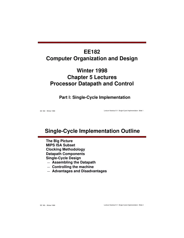
IFU at the End of Jump

30 30 SignExt 30 16 imm16 Mux 1 Adder “1” PC Clk Adder 30 30 Branch = 0 Zero = x “00” Addr<31:2> Instruction Memory Addr<1:0> 32 Mux 1 26 4 PC<31:28> Target 30

PC <- PC<31:29> concat target<25:0> concat “00”

Jump = 1 Instruction<15:0> Instruction<31:0> 30 Instruction<25:0>

Lecture Handout 5-1: Single-Cycle Implementation Slide 44 EE 182 -- Winter 1989

Summary of Control Signals

add sub

  • ri

lw sw beq jump RegDst ALUSrc MemtoReg RegWrite MemWrite Branch Jump ExtOp ALUctr<2:0>

1 1 x Add 1 1 x Subt 1 1 Or 1 1 1 1 Add x 1 x 1 1 Add x x 1 x Subt x x x 1 x xxx

  • p

target address

  • p

rs rt rd shamt funct 6 11 16 21 26 31

  • p

rs rt immediate R-type I-type J-type add, sub

  • ri, lw, sw, beq

jump func

  • p 00 0000 00 0000 00 1101 10 0011 10 1011 00 0100 00 0010

Appendix A for coding

(Fig A.19 has an error for lw, sw)

10 0000 10 0010

We Don’t Care :-)

slide-23
SLIDE 23

Lecture Handout 5-1: Single-Cycle Implementation Slide 45 EE 182 -- Winter 1989

The Concept of Local Decoding

R-type

  • ri

lw sw beq jump RegDst ALUSrc MemtoReg RegWrite MemWrite Branch Jump ExtOp ALUop<N:0> 1 1 x “R-type” 1 1 Or 1 1 1 1 Add x 1 x 1 1 Add x x 1 x Subtract x x x 1 x xxx

  • p

00 0000 00 1101 10 0011 10 1011 00 0100 00 0010

Main Control

  • p

6 ALU Control (Local) func N 6 ALUop ALUctr 3 ALU

Decode some control lines in two steps

Lecture Handout 5-1: Single-Cycle Implementation Slide 46 EE 182 -- Winter 1989

The Encoding of ALUop

In this exercise, ALUop is 2 bits wide to represent:

— (1) “R-type” instructions — “I-type” instructions that require the ALU to perform:

  • (2) Or, (3) Add, and (4) Subtract

To implement full MIPS ISA from Chap 3, ALUop has 3 bits:

— (1) “R-type” instructions — “I-type” instructions that require the ALU to perform:

  • (2) Or, (3) Add, (4) Subtract, and (5) And (Example: andi)

Main Control

  • p

6 ALU Control (Local) func N 6 ALUop ALUctr 3 R-type

  • ri

lw sw beq jump ALUop (Symbolic) “R-type” Or Add Add Subt xxx ALUop<2:0> 1 00 0 10 0 00 0 00 0 01 xxx

slide-24
SLIDE 24

Lecture Handout 5-1: Single-Cycle Implementation Slide 47 EE 182 -- Winter 1989

Decoding the “func” Field

R-type

  • ri

lw sw beq jump ALUop (Symbolic) “R-type” Or Add Add Subt xxx ALUop<2:0> 1 00 0 10 0 00 0 00 0 01 xxx Main Control

  • p

6 ALU Control (Local) func N 6 ALUop ALUctr 3

  • p

rs rt rd shamt funct 6 11 16 21 26 31 R-type funct<5:0> Instruction Operation 10 0000 10 0010 10 0100 10 0101 10 1010 add subtract and

  • r

set-on-less-than ALUctr<2:0> ALU Operation 000 001 010 110 111 And Or Add Subtract Set-on-less-than

(Differs slightly from text figure 4.20) ALUctr ALU

Lecture Handout 5-1: Single-Cycle Implementation Slide 48 EE 182 -- Winter 1989

Truth Table for ALUctr

R-type

  • ri

lw sw beq ALUop (Symbolic) “R-type” Or Add Add Subt ALUop<2:0> 1 00 0 10 0 00 0 00 0 01 ALUop func bit<2>bit<1>bit<0> bit<2>bit<1>bit<0> bit<3> x x x x ALUctr ALU Operation Add 1 bit<2>bit<1>bit<0> x 1 x x x x Subtract 1 1 1 x x x x x Or 1 1 x x Add 1 1 x x 1 Subtract 1 1 1 x x 1 And 1 x x 1 1 Or 1 1 x x 1 1 Set on < 1 1 1 funct<3:0> Instruction Op. 0000 0010 0100 0101 1010 add subtract and

  • r

set-on-less-than

slide-25
SLIDE 25

Lecture Handout 5-1: Single-Cycle Implementation Slide 49 EE 182 -- Winter 1989

Logic Equation for ALUctr<2>

ALUop func bit<2>bit<1>bit<0> bit<2>bit<1>bit<0> bit<3> ALUctr<2> x 1 x x x x 1 1 x x 1 1 1 x x 1 1 1

ALUctr<2> = ~ALUop<2> • ALUop<0> + ALUop<2> • ~func<2> • func<1> • ~func<0>

This makes func<3> a don’t care

Lecture Handout 5-1: Single-Cycle Implementation Slide 50 EE 182 -- Winter 1989

Logic Equation for ALUctr<1>

ALUop func bit<2>bit<1>bit<0> bit<2>bit<1>bit<0> bit<3> x x x x 1 ALUctr<1> x 1 x x x x 1 1 x x 1 1 x x 1 1 1 x x 1 1 1

ALUctr<1> = ~ALUop<2> • ~ALUop<1> + ALUop<2> • ~func<2> • ~func<0>

slide-26
SLIDE 26

Lecture Handout 5-1: Single-Cycle Implementation Slide 51 EE 182 -- Winter 1989

The Logic Equation for ALUctr<0>

ALUop func bit<2>bit<1>bit<0> bit<2>bit<1>bit<0> bit<3> ALUctr<0> 1 x x x x x 1 1 x x 1 1 1 1 x x 1 1 1

ALUctr<0> = ~ALUop<2> • ALUop<0> + ALUop<2> • ~func<3> • func<2> • ~func<1> • func<0> + ALUop<2> • func<3> • ~func<2> • func<1> • ~func<0>

Lecture Handout 5-1: Single-Cycle Implementation Slide 52 EE 182 -- Winter 1989

ALU Control Block

ALU Control (Local) func 3 6 ALUop ALUctr 3

ALUctr<2> = ~ALUop<2> • ALUop<0> + ALUop<2> • ~func<2> • func<1> • ~func<0> ALUctr<1> = ~ALUop<2> • ~ALUop<1> + ALUop<2> • ~func<2> • ~func<0> ALUctr<0> = ~ALUop<2> • ALUop<0> + ALUop<2> • ~func<3> • func<2> • ~func<1> • func<0> + ALUop<2> • func<3> • ~func<2> • func<1> • ~func<0>

slide-27
SLIDE 27

Lecture Handout 5-1: Single-Cycle Implementation Slide 53 EE 182 -- Winter 1989

Truth Table for Main Control

R-type

  • ri

lw sw beq jump RegDst ALUSrc MemtoReg RegWrite MemWrite Branch Jump ExtOp ALUop (Symbolic) 1 1 x “R-type” 1 1 Or 1 1 1 1 Add x 1 x 1 1 Add x x 1 x Subt x x x 1 x xxx

  • p

00 0000 00 1101 10 0011 10 1011 00 0100 00 0010

ALUop <2> 1 x ALUop <1> 1 x ALUop <0> 1 x

Main Control

  • p

6 ALU Control (Local) func 3 6 ALUop ALUctr 3 RegDst ALUSrc

:

Lecture Handout 5-1: Single-Cycle Implementation Slide 54 EE 182 -- Winter 1989

Truth Table for RegWrite

R-type

  • ri

lw sw beq jump RegWrite 1 1 1

  • p

00 0000 00 1101 10 0011 10 1011 00 0100 00 0010

RegWrite = R-type + ori + lw

= ~op<5> • ~op<4> • ~op<3> • ~op<2> • ~op<1> • ~op<0> (R-type) + !op<5> & !op<4> & op<3> & op<2> & !op<1> & op<0> (ori) + op<5> & !op<4> & !op<3> & !op<2> & op<1> & op<0> (lw)

  • p<0>
  • p<5>

..

  • p<5>

..

<0>

  • p<5>

..

<0>

  • p<5>

..

<0>

  • p<5>

..

<0>

  • p<5>

..

<0> R-type

  • ri

lw sw beq jump RegWrite

slide-28
SLIDE 28

Lecture Handout 5-1: Single-Cycle Implementation Slide 55 EE 182 -- Winter 1989

PLA Implementation of Control

  • p<0>
  • p<5>. .
  • p<5>. .

<0>

  • p<5>. .

<0>

  • p<5>. .

<0>

  • p<5>. .

<0>

  • p<5>. .

<0> R-type

  • ri

lw sw beq jump RegWrite ALUSrc MemtoReg MemWrite Branch Jump RegDst ExtOp ALUop<2> ALUop<1> ALUop<0>

Lecture Handout 5-1: Single-Cycle Implementation Slide 56 EE 182 -- Winter 1989

Control Implementation Choices

Programmable Logic Arrray (PLA) vs. “Random” Logic

— Design Changes

  • Changes resulting from validation are common
  • PLA is less work to change; area/timing impact is predictable

— Area

  • Tradeoff depends on complexity of logic (# gates and interconnect)

— Timing and Power

  • Random logic generally better since individual paths can be tuned

Another approach is Read-Only Memory (ROM)

— “Microcode” is covered in next section on multi-

cycle implementation

slide-29
SLIDE 29

Lecture Handout 5-1: Single-Cycle Implementation Slide 57 EE 182 -- Winter 1989

Putting it All Together: Single Cycle Processor

32 ALUctr Clk busW RegWr 32 32 busA 32 busB 5 5 5 Rw Ra Rb 32 32-bit Registers Rs Rt Rt Rd RegDst Extender Mux Mux 32 16 imm16 ALUSrc ExtOp Mux MemtoReg Clk Data In WrEn 32 Adr Data Memory 32 MemWr ALU Instruction Fetch Unit Clk Zero Instruction<31:0> Jump Branch 1 1 1 <21:25> <16:20> <11:15> <0:15> Imm16 Rd Rs Rt Main Control

  • p

6 ALU Control func 6 3 ALUop ALUctr 3 RegDst ALUSrc

:

Instr<5:0> Instr<31:26> Instr<15:0>

Lecture Handout 5-1: Single-Cycle Implementation Slide 58 EE 182 -- Winter 1989

Abstract View of Critical Path

Clk 5 Rw Ra Rb 32 32-bit Registers Rd ALU Clk Data In DataOut Data Address Ideal Data Memory Instruction Instruction Address Ideal Instruction Memory Clk PC 5 Rs 5 Rt 16 Imm 32 32 32 32 Critical Path (Load Operation) = PC’s Clk-to-Q + Instruction Memory’s Access Time + Register File’s Access Time + ALU to Perform a 32-bit Add + Data Memory Access Time + Setup Time for Register File Write + Clock Skew

slide-30
SLIDE 30

Lecture Handout 5-1: Single-Cycle Implementation Slide 59 EE 182 -- Winter 1989

Drawback of Single-Cycle Processor

Long cycle time

— Cycle time must be long enough for load instruction:

  • PC’s Clock-to-Q +
  • Instruction Memory Access Time +
  • Register File Access Time +
  • ALU Delay (address calculation) +
  • Data Memory Access Time +
  • Register File Setup Time +
  • Clock Skew

Cycle time >> that needed for all other instructions

— Cycle time is fixed at worst-case for all instructions

Logic is poorly utilized

— ALU actively computing results for only a small

portion of the clock cycle

Useful teaching example, but too slow & costly for real use!