
SLIDE 1
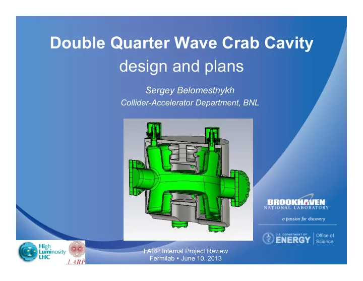
Double Quarter Wave Crab Cavity design and plans
Sergey Belomestnykh
Collider-Accelerator Department, BNL
LARP Internal Project Review Fermilab June 10, 2013
Double Quarter Wave Crab Cavity design and plans Sergey Belomestnykh - - PowerPoint PPT Presentation
Double Quarter Wave Crab Cavity design and plans Sergey Belomestnykh Collider-Accelerator Department, BNL LARP Internal Project Review Fermilab June 10, 2013 Outline Proof-of-Principle (PoP) design PoP cavity testing
LARP Internal Project Review Fermilab June 10, 2013
June 10, 2013
2
A compact double quarter-wave geometry.
June 10, 2013
3
Frequency 400 MHz Deflecting Voltage 3.0 MV Rt /Q (Fund. Mode) 400 Ohm G 88.3 Ohm RBCS (2 K) 1 nOhm RBCS (4.5 K) 62.3 nOm Rres 10 nOhm Q0 (2 K) 8.0×10⁹ Q0 (4.5 K) 1.2×10⁹ PRF 2.8 W Dynamic liquefaction load 0.13 g/s Cavity length flange-to-flange is 551 mm
§
A proof-of-principle cavity has been fabricated by Niowave: no helium vessel, just stiffeners.
§
Ti stiffening frame to allow pressure differential up to 2 bar.
§
Nb to Ti transition via serrated surface plus SS bolts.
§
SS bolts and pins at frame connections.
June 10, 2013
4
PoP cavity with stiffeners
June 10, 2013
5
June 10, 2013
6
June 10, 2013
7
June 10, 2013
8
stand, installation of the FPC and pick-up probe, mounting DQWCC to the top plate);
calibration.
June 10, 2013
9
Mounting Rods (x4) FPC Actuator Drive & Linkage Drive Shaft Bellows with Conflat flanges § The pickup antenna was set to be 20.7±0.5 mm away from the cavity (Qext of 8.8×10¹⁰ to 1.2×10¹¹). § The FPC is 8.7 mm away from the cavity, with a tuning range at ±10 mm (Qext of 1.8×10⁸ to 5.7×10¹⁰). RF pickup
June 10, 2013
10
Block house and control area Mounting linkage parts Cavity in clean room Cavity under top plate FPC motion linkage Cavity and testing dewar
June 10, 2013
11
§ Upon RF turn-on encountered multipacting barrier at ~0.1 MV, which was conditioned easily. § Q is low, ~3×10⁸ and is independent on the temperature è very high residual loss. This cannot be accounted for with losses in stainless steel blank flanges of FPC. § Q did not change after slow cooldown è no hydrogen Q-disease. § In CW mode could not reach more than 0.96 MV due to thermal quench (~80 W dissipated in the cavity). § Observed temperature rise only on the sensor attached to the top flange – local defect – material inclusion, residue after BCP/HPR…? § In pulsed mode reached 1.34 MV, limited by 200 W RF amplifier. § Cavity vacuum stayed good throughout the test. Multipacting processing Cavity temperature increases Slow recovery Pulsed
June 10, 2013
12
§ Cavity length along beam pipe (with 4 mm wall thickness included): 390 mm § Cavity width perpendicular to beam pipe (with 4 mm wall thickness included): 295 mm § Gap between cavity outer surface and nearby beam pipe outer surface: 1.24 mm # of ports total: 6 # of HOM couplers: 4 Inner diameter of all coupler ports: 28 mm
June 10, 2013
13
Gap [mm]: 1.2 5.3 8.3 Cavity width @ waist [mm]: 147.5 143.4 140.4 Cavity length [mm]: 390 405 449 Ep/Bp @ 3.3MV [(MV/m)/mT] 44/62 42/63 38/69
June 10, 2013
14
Peak B field @ FPC port: 67 mT for 3.3 MV deflection voltage
June 10, 2013
15
§ Modified from BNL HOM filter for 56 MHz SRF Quarter Wave Cavity. § Study of HOM port number / location.
Scheme: I III II Loop size: 20 mm × 15 mm
June 10, 2013
16
Scheme: II V IV
June 10, 2013
17
0.579 Longitudinal 108 864 1360 1770 0.671 Horizontal 70.5 1526 3080 3260 0.700 Hybrid (y, z) 0.24/0.25 929 1310 2210 0.752 Deflection 34.9 1418 2020 3350 0.800 Horizontal 6.02e-4 2074 4120 4630 0.917 Horizontal 30.9 1345 2660 1.88e8 0.949 Longitudinal 28.1 3183 3360 2220 1.080 Deflection 1.54 1071 1350 1920 1.102 Horizontal 1.84e-3 902 1490 2350 1.114 Deflection 1.06 2663 5040 2630 1.202 Horizontal 5.07e-2 5021 11000 8980 1.247 Hybrid (y, z) 8.0e-2/6.0e-2 1373 1970 2920 1.291 Deflection 10.0 778 1060 1450 1.353 Horizontal 2.46e-4 951 2060 6730 1.408 Deflection 9.84e-3 3480 10100 2760
June 10, 2013
18
0.579 Longitudinal 108 1360 1020 1021 0.671 Horizontal 70.5 3080 1521 1569 0.700 Hybrid (y, z) 0.24/0.25 1310 1191 1193 0.752 Deflection 34.9 2020 1826 1843 0.800 Horizontal 6.02e-4 4120 2080 2054 0.917 Horizontal 30.9 2660 1330 1359 0.949 Longitudinal 28.1 3360 6712 6703 1.080 Deflection 1.54 1350 1577 1389 1.102 Horizontal 1.84e-3 1490 959 819 1.114 Deflection 1.06 5040 2994 2646 1.202 Horizontal 5.07e-2 11000 5460 5525 1.247 Hybrid (y, z) 8.0e-2/6.0e-2 1970 1969 1978 1.291 Deflection 10.0 1060 1198 1209 1.353 Horizontal 2.46e-4 2060 1040 3800 1.408 Deflection 9.84e-3 10100 1040 12200
June 10, 2013
19
Filter design goals: § High attenuation at 400 MHz § High transmission @ all HOM frequencies § Efficient and sufficient cooling § Compact design, no interference with other components § Practical fabrication § As universal as possible to all versions § Meet with the schedule 7.6 cm 6.6 cm
Temporary design for required inductance value, will change to avoid high field and thermal issue.
June 10, 2013
20
June 10, 2013
21
§
Helium vessel concept:
bellows for tuning.
with stress relief.
§
Frequency tuner:
& piezo drivers
June 10, 2013
22
June 10, 2013
23
§
Requirement: Less than 1 µT on cavity surface
§
Magnetic field 48 µT: Vertical 44 µT, Horizontal 20 µT (//pipe)
§
Material: 2 mm Cryoperm10 with µr = 150000
§
Shield cavity, vessel, and loose fit to beam pipe
June 10, 2013
24
§
Take the PoP cavity off the test stand, inspect, re-process and re-test.
§
Finalize the cavity geometry & parameters to satisfy SPS functional specs.
§
Optimize HOM coupler and filter.
mechanical tolerances, manufacturability, assembly sequence.
§
Design the DQWCC tuner and helium vessel for SPS beam test
§
Nearest goals:
§
Collaborations:
etc.
design.
June 10, 2013
25
June 10, 2013
26