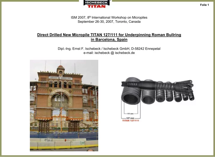

Folie 1 ISM 2007, 8 th International Workshop on Micropiles September 26-30, 2007, Toronto, Canada Direct Drilled New Micropile TITAN 127/111 for Underpinning Roman Bullring in Barcelona, Spain Dipl.-Ing. Ernst F. Ischebeck / Ischebeck GmbH, D-58242 Ennepetal e-mail: ischebeck @ ischebeck.de
Folie 2 Micropile TITAN – Main Components Concrete structure Pile Head Smooth HD-PE Pipe active Zone Filtercake (Diaphragma) Slip plane passive Zone Grout Body min. cement stone cover 20 to 50 mm Consolidated Soil Filtercake Cement stone D > 2,0 x d gravel 1,5 x d sand 1,4 x d Sand-clay Steel member d 1,0 x d wheathered clay stone, shale D
Folie 3 Self-Drilling and Dynamic Grouted Micropiles TITAN Drilling and flushing with cement grout w/c = 0,7 - 1,0 without temporary casing w/c ~ 0,7 10 -20 bar In one step tremi grouting of cement w/c~ 0,4 with simultaneous rotation of tremi is called „Dynamic Grouting“ Micropile Diameter D = 1,0 ÷ 2,0 x drill bit diameter depending on type of soil w/c ~ 0,4 20 - 60 bar
Folie 4 Load Transfer in Composite Micropiles TITAN for one Homogenous Layer of Soil Distribution of Pile Forces over Pile Length Headplate Monitoring the Distribution of Load Transfer 0 Concrete to the Soil by Extensometers, installed inside Foundation the hollow Micropile TITAN 1 PE Plastic Tube Tendon TITAN Grout Body qs1= Interface 2 x qs2 Soil Grout Body/ Soil Confined 2 qs2 3
Folie 5 Inner Capacity of Composite Micropiles to avoid Splitting e.g. TITAN 30/11 For A c ≥ 0,85 and Yield Stress of Tendon ≤ 550 Mpa Circular Force R A A A c is balanced Total Micropile Grout Cross Section Cross Section HD-PE Tube min. length to balance the load F to Steel and Concrete Section acc. to the Stiffness Relation Important! Axial Crack not allowed! Necessary Length 0 – 1 for Load Transfer F from Tendon to Grout Body Circular Force R in Grout Body, caused by - Different Poisson ratio and - Shear Bond Circular Force R has to be balanced to avoid Axial Cracks
Folie 6 Micropiles TITAN 40/16 are included in the FRENCH NATIONAL RESEARCH PROJECT (FOREVER) to improve design of single and reticulated micropiles. Several tests on natural size (size 1:1) in St-REMY-LES-CHEVREUSE in 1998, all with loose, fine and dry sand of Fontainebleau Micropiles TITAN 40/16, length 5 m, drill bit 70 mm, flushing grout w/c=0,9, grout pressure 8 - 20 bar Results: 4. No visible cracks observed in the grout body 1. Skin friction qs = 74 kN/m² Micropiles TITAN fulfil 5. Steel member centered in the grout requirements of French body DTU 13.2 micropieux Typ IV (IRS or postgrouted) 6. Dynamical testing of integrity and length of micropiles TITAN by 2. In compression 7% loadtransfer French method SIMBAT works and by end bearing, 93% by friction is confirmed by CEBTP 3. Micropile Diameter D=113 mm Drill bit d= 70 mm, D = (1,5 ÷ 1,8) x d
Folie 7 Belgium National Research Program Groundanchors BBRI Research, Limelette in 2006-2007 The site with a glacial profile offers: sand, gravel, clay 7 types Micropiles TITAN 73/45, 18 m long, are included. Each equipped with 7 extensometers.
Folie 8 Still Existing Facade of Bullring
Folie 9 Vision of New Building Contractor: DRAGADOS excavation ' 18 m 0 6 Old Facade integrated in New Structure, Office Building with Parking
Folie 10 Soil Investigation
Folie 11 Soil Investigation Estimated vertical Displacement 8 to 12 mm 18 m Excavation New Base Plate - water level
Folie 12 Free standing facade of bullring, supported by micropiles and braced by framework. Beginning of excavation.
Folie 13 Details of temporary support.
Folie 14 Step by step with excavation the 4 freestanding micropiles TITAN are braced. The braces are not welded; but the connection-houses are filled with grout.
Folie 15 The facade is suspended. The micropiles are installed in the free area of the facade (arches). The weight of the facade is supported by 2 concrete beams, parallel outside and inside the facade, which are clamped together with the facade by prestressing strands.
Folie 16 Suspended old facade. Load transfer by 2 concrete beams to the braced micropiles.
Folie 17 Heavy structure of the portal suspended by beams. Beams are supported by micropiles.
Folie 18 Starting Underpinning in the Openings under the Arches. Access for the drilling machine.
Folie 19 Difficult Access for Drilling and Grouting the Micropiles.
Folie 20 2. Site Deep Excavation in Downtown Barcelona Creating additional Space For Parking Underground. Micropile Wall
Folie 21
Folie 22 WIDE less less than than 4,5 m. 4,5 m. WIDE Small Access to the Site in Downtown.
Folie 23
Folie 24 Distance of Micropiles TITAN 127/111: 3 pcs. per m. Distance of Walers: 4,5 m Ground: Sand, Schist, φ = 35 °, C u = 100 kN/m², no water
Folie 25 Installing the micropiles very close - 0,3 m distance - to the existing wall. Stock of micropiles TITAN 127/111, 3 m long, bundles of 10 pieces.
Folie 26 Construction of the waler in reinforced concrete. No loose in load transfer. The gap between the micropiles can be closed with shotcrete added with epoxy resin, if there is high watertable.
Folie 27 Existing Foundations or obstacles are penetrated by the micropiles.
Folie 28 Anchored Micropiles in Micropiles in Uncontinuous Uncontinuous Diaphragm Diaphragm Walls Walls, , Anchored in confined confined areas areas, , taking taking bending bending moments moments. . in
Folie 29 Protection of Circular Deep Excavation Shaft by Micropile Wall under Flyover. Existing Heavy Low Headroom Structure (Bridge Pier) Head Beam Secant Micropile Wall
Folie 30 Micropiles with bending resistance work as drilled sheet piles.
Recommend
More recommend