
SLIDE 1
Diffraction
Light bends! Diffraction assumptions Solution to Maxwell's Equations The far-field
Fraunhofer Diffraction Some examples
Diffraction Light bends! Diffraction assumptions Solution to - - PowerPoint PPT Presentation
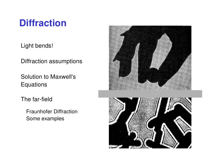
Diffraction Light bends! Diffraction assumptions Solution to Maxwell's Equations The far-field Fraunhofer Diffraction Some examples Diffraction Shadow of a Light does not hand illuminated always travel in a by a straight line.
Diffraction
Light bends! Diffraction assumptions Solution to Maxwell's Equations The far-field
Fraunhofer Diffraction Some examples
Diffraction
Light does not always travel in a straight line. It tends to bend around objects. This tendency is called diffraction. Any wave will do this, including matter waves and acoustic waves.
Shadow of a hand illuminated by a Helium- Neon laser Shadow of a zinc oxide crystal illuminated by a electrons
Why it’s hard to see diffraction
Diffraction tends to cause ripples at edges. But poor source temporal or spatial coherence masks them. Example: a large spatially incoherent source (like the sun) casts blurry shadows, masking the diffraction ripples. Untilted rays yield a perfect shadow of the hole, but off-axis rays blur the shadow. Screen with hole A point source is required.
Diffraction of a wave by a slit
Whether waves in water or electromagnetic radiation in air, passage through a slit yields a diffraction pattern that will appear more dramatic as the size of the slit approaches the wavelength of the wave.
λ ≈ slit size λ slit size λ < slit size
Diffraction of ocean water waves
Ocean waves passing through slits in Tel Aviv, Israel Diffraction occurs for all waves, whatever the phenomenon.
Light passing by edge
Diffraction by an Edge
Electrons passing by an edge (Mg0 crystal)
x
Transmission
Even without a small slit, diffraction can be strong. Simple propagation past an edge yields an unintuitive irradiance pattern.
Radio waves diffract around mountains.
When the wavelength is km long, a mountain peak is a very sharp edge! Another effect that occurs is scattering, so diffraction’s role is not obvious.
Diffraction Geometry
We wish to find the light electric field after a screen with a hole in it. This is a very general problem with far-reaching applications. What is E(x1,y1) at a distance z from the plane of the aperture?
Incident wave
This region is assumed to be much smaller than this one.
x1 x0
P1
A(x0,y0) y1 y0
Diffraction Solution
The field in the observation plane, E(x1,y1), at a distance z from the aperture plane is given by:
( ) ( )
1 1 1 1 ( , ) 01 1 1 01 2 2 2 01 1 1
( , , ) ( , , ) ( , ) exp( ) 1 ( , , )
A x y
E x y z h x x y y z E x y dx dy ikr h x x y y z i r r z x x y y λ = − − − − = = + − + −
where : and :
A very complicated result! And we cannot approximate r01 in the exp by z because it gets multiplied by k, which is big, so relatively small changes in r01 can make a big difference! Spherical wave
Fraunhofer Diffraction: The Far Field
( ) ( ) ( )
2 2 1 1 1 1 0 1 1 ( , )
exp( ) , exp exp , 2
A x y
x y ikz ik E x y ik x x y y E x y dx dy i z z z λ + = − + ∫∫
We can approximate r01 in the denominator by z, and if D is the size of the aperture, D 2 ≥ x0
2 + y0 2, so when k D2/ 2z << 1, the quadratic terms <<
1, so we can neglect them: This condition means going a distance away: z >> kD2/2 = πD2/λ If D = 1 mm and λ = 1 micron, then z >> 3 m.
( ) ( ) ( ) ( )
2 2 2 2 2 2 2 01 1 1 1 1
1 / 2 / 2 r z x x y y z x x z y y z = + − + − ≈ + − + −
( ) ( )
2 2 2 2 01 1 1 1 1
2 / 2 2 / 2 kr kz k x x x x z k y y y y z ≈ + − + + − +
Independent of x0 and y0, so factor these out. Small, so neglect these terms.
Fraunhofer Diffraction
We’ll neglect the phase factors, and we’ll explicitly write the aperture function in the integral:
( ) ( )
1 1 0 1 1
, exp ( , ) ( , ) ik E x y x x y y A x y E x y dx dy z
∞ ∞ −∞ −∞
∝ − +
This is just a Fourier Transform! Interestingly, it’s a Fourier Transform from position, x0, to another position variable, x1 (in another plane). Usually, the Fourier “conjugate variables” have reciprocal units (e.g., t & ω, or x & k). The conjugate variables here are really x0 and kx = kx1/z, which have reciprocal units. So the far-field light field is the Fourier Transform of the apertured field!
E(x0,y0) = constant if a plane wave
The Fraunhofer Diffraction formula
where we’ve dropped the subscripts, 0 and 1,
( ) ( )
, exp ( , ) ( , )
x y x y
E k k i k x k y A x y E x y dxdy
∞ ∞ −∞ −∞
∝ − +
E(x,y) = const if a plane wave Aperture function
We can write this result in terms of the off-axis k-vector components:
kx = kx1/z and ky = ky1/z ( )
{ }
, ( , ) ( , )
x y
E k k A x y E x y ∝ F
kz ky kx
θx = kx/k = x1/z and θy = ky/k = y1/z
and:
The Uncertainty Principle in Diffraction!
Because the diffraction pattern is the Fourier transform of the slit, there’s an uncertainty principle between the slit width and diffraction pattern width! If the input field is a plane wave and ∆x = ∆x0 is the slit width,
( )
{ }
, ( , ) ( , )
x y
E k k A x y E x y ∝ F
1
x
x k ∆ ∆ >
1
/ x x z k ∆ ∆ >
kx = kx1/z
Or: The smaller the slit, the larger the diffraction angle and the bigger the diffraction pattern!
Fraunhofer Diffraction from a slit
Fraunhofer Diffraction from a slit is simply the Fourier Transform of a rect function, which is a sinc function. The irradiance is then sinc2 .
Fraunhofer Diffraction from a Square Aperture
The diffracted field is a sinc function in both x1 and y1 because the Fourier transform of a rect function is sinc.
Diffracted irradiance Diffracted field
Diffraction from a Circular Aperture
A circular aperture yields a diffracted "Airy Pattern," which involves a Bessel function. Diffracted field Diffracted Irradiance
Diffraction from small and large circular apertures
Recall the Scale Theorem! This is the Uncertainty Principle for diffraction. Far-field intensity pattern from a small aperture Far-field intensity pattern from a large aperture
Fraunhofer diffraction from two slits
A(x0) = rect[(x0+a)/w] + rect[(x0-a)/w] x0 a
1
( ) { ( )} E x A x ∝ F
1 1 1 1
sinc[ ( / ) / 2]exp[ ( / )] sinc[ ( / ) / 2]exp[ ( / )] w kx z ia kx z w kx z ia kx z ∝ + + −
1 1 1
( ) sinc( / 2 ) cos( / ) E x wkx z akx z ∝
kx1/z
w w
Diffraction from one- and two-slit screens
Fraunhofer diffraction patterns One slit Two slits
Diffraction Gratings
when light impinges on a periodic array of
the delay between adjacent beamlets is an integral number, m, of wavelengths.
[ ]
sin( ) sin( )
m i
a m θ θ λ − =
where m is any integer. A grating has solutions of zero, one, or many values of m, or orders. Remember that m and θm can be negative, too. Path difference: AB – CD = mλ Scatterer Scatterer a θi θm a AB = a sin(θm) CD = a sin(θi) A D C B Potential diffracted wave-front Incident wave-front θi θm
Diffraction orders
Because the diffraction angle depends on λ, different wavelengths are separated in the nonzero orders. No wavelength dependence
The longer the wavelength, the larger its deflection in each nonzero
Diffraction angle, θm(λ) Zeroth order First order Minus first
Incidence angle, θi
Diffracted white light White light diffracted by a real grating. m = m =1 m = 2 m =
The dots on a CD are equally spaced (although some Diffractio n gratings
Lawrence Livermore National Lab