
SLIDE 1
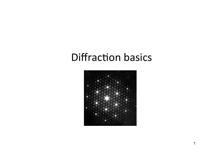
Diffrac'on basics
1
Diffrac'on basics 1 Diffraction Diffraction refers to the - - PowerPoint PPT Presentation
Diffrac'on basics 1 Diffraction Diffraction refers to the phenomena exhibited by radiation when it interacts with barriers and obstacles (scattering). Interference of waves Diffrac'on is construc've interference of light rays or other types of
1
Construc've interference: mutual reinforcement of the sca9ered rays
various parallel beams are a mul'ple of wavelength: Δd = n*λ
Destruc've interference: sca9ered beams are out of phase and cancel each other.
various parallel beams are a mul'ple
3
So?
This chapter is a direct con'nua'on of the previous one, although the name has been changed from Interference to Diffrac'on. No one has ever been able to define the difference between interference and diffrac5on sa5sfactorily. It is just a ques'on of usage, and there is no specific, important physical difference between them. The best we can do, roughly speaking, is to say that when there are only a few sources, say two, interfering, then the result is usually called interference, but if there is a large number of them, it seems that the word diffrac5on is more o<en used. So, we shall not worry about whether it is interference or diffrac'on, but con'nue directly from where we leK off in the middle of the subject in the last chapter.
4
5
Every point on a propagating wavefront serves as the source of spherical secondary wavelets, such that the wavefront at a later time is the envelope
The image shows a wavefront, as well as a number of spherical secondary wavelets, which after a time t, have propagated out to a radius of vt. The envelop of all these wavelets is then asserted to correspond to the advanced primary wave.
Propagation of a wavefront according to Huygens’s principle: consistent with diffraction
The wavelets advance with a speed and frequency equal to those of the primary wave at each point in space.
6
What can be said about the symmetry of this diffraction pattern?
7
Interference is construc've only if the radia'on is coherent. A diffrac'on pa9ern results from diffrac'on (sca9ering) followed by interference between the diffracted (sca9ered) beams. Diagram of a distant light source emiQng coherent wavetrains. When one of these strikes a screen with adjacent slits, the slits act as secondary sources of light according to Huygen’s principle, which then meet and interfere.
8
9
10
Slit width (a) several times the wavelength (λ): Locate the first minima
11
Slit width (a) several times the wavelength (λ): Locate the first minima Virtual point sources
2 2
Condi'on for maxima in the interference plane: mλ = d sinθ
Reciprocal relation between θ and d…
with m = 0, ±1, ±2, …
12
Side view of a diffrac'on gra'ng. The slit separa'on is d and the path difference between adjacent slits is d sinθ.
m is the order of diffraction.
Observa'ons of diffrac'on of light using a laser as a coherent light source. As the aperture size decreases the diameter of the diffracted disk and rings increases (reciprocal rela'on...)
(a) (c) (b) (e) (d) 13
Any point of the reciprocal laQce can be specified by a vector: dhkl
* = ha* + kb* + lc*
This vector is perpendicular to the plane in real space with Miller indices (hkl). The length
* |= 1/dhkl where dhkl is the interplanar spacing in real space.
Designations:
Designations:
(spatial not temporal)
The reciprocal laQce is a set of imaginary points so that the direc'on of a vector from one point to another coincides with the normal to a family of real space planes. The absolute value of the vector is given by the reciprocal of the real interplanar distance. A whole family of planes in real space is represented by a s i n g l e p o i n t i n reciprocal space
14
Construction of reciprocal lattice
and (001).
inverse of the distance from the origin to the direct space planes.
15
defined in geometry: mathema'cal en''es.
and has dimensions of m, whereas the reciprocal laEce can be used to indicate the posi'on of diffracted light/radia5on spots and has dimensions of m-1.
contrast to real space or direct space.
Fourier transforms.
diffracted intensity at each reciprocal point is determined by the mo've or base.
16
The reciprocal laQce is related to the real space laQce by:
vectors of the reciprocal laQce.
(unit cell volume)
the reciprocal laQce is the direct laQce.
17
V = a.(b∗ ×c∗)
defined in geometry: mathema'cal en''es.
and has dimensions of m, whereas the reciprocal laEce can be used to indicate the posi'on of diffracted light spots and has dimensions of m-1.
contrast to real space or direct space.
Fourier transforms.
diffracted intensity at each reciprocal point is determined by the mo've or base.
18
to a widely-spaced ver'cal row of points.
gives rise to a more closely-spaced row of points perpendicular to these lines.
give an array of points at the intersec'ons of the lines in the bo9om part of the figure.
was obtained by mul'plying two sets of lines, is the convolu'on of the two individual transforms (i.e. rows of points) , which generates a reciprocal laQce.
(in this context the period refers to interplanar distance, not 'me)
19
Both spaces are periodic and with the same symmetry, so:
20
Amplitude (measure of intensity at each point in recirpocal space)) Spatial frequency (position in the diffraction pattern)
x-rays off of "planes" of regularly arranged atoms. Incident beams are ‘reflected’ in phase if the path difference between them equals an integer multiple of the wavelength:
21
Postulate:
beam vector at the sphere center,
Then: |S - S0| = 2 R sinθ = 2 sinθ /λ Only when S - S0 coincides with a reciprocal laQce point (i.e. when |S - S0| = |d*hkl|= 1/dhkl ) is Bragg’s law sa'sfied: 2 sinθ /λ = 1/dhkl Therefore construc've interference occurs when S - S0 coincides with the reciprocal vector of the reflec'ng planes!
22
For this incident angle there is no diffracted intensity ! Notation: d*hkl = ghkl
A change in the orienta'on of the incident beam rela've to the crystal changes the
Eventually a condi'on where diffrac'on occurs. A change in λ changes the sphere radius and may also be used to sa'sfy Bragg’s law.
The limiting sphere is obtained by the rotation around the origin of the reflection (Ewald) sphere. Defines the possible ‘reflections’ in a diffractogram, which depend only on the wavelength (radius
radiation with λ wavelength due to too small interplanar distances…
24
25
Assume a row of scatterers separated by constant repeat, a. Radiation of wavelength λ is incident on this row at an angle αo. Examine the the scatter from this row at an angle αn. The path difference of rays scattering from points A and D is just AB-CD. If the incoming rays are in phase, the path difference must be some integer multiple of the wavelength for constructive interference to occur. This leads to the first Laue equation:
26
In reality the angle αn does not need to be measured only as θ in Bragg’s law
(αn in constant on the conical surface).
27
Laue's remarkable idea was that this equation must have a simultaneous solution with the equation written for the x direction (and the z direction as well). The solution to this second equation also forms a cone except this time about b. The simultaneous solution to these two equations can be viewed as the intersection of the two cones originating at a common apex and which intersect along two lines.
28
Next consider another row of scatterers at some angle, to the first with repeat distance, b. A second Laue equation can be written for this direction. The incident rays will make angle β0 to this row and the scattered rays βn. This equation must also result in some integer multiple of the wavelength, ny, for constructive interference to occur.
29
Adding scatterers in a third direction to form a 3D lattice gives the third Laue equation. This results in a set of equations with one simultaneous solution. By analogy with the previous results this solution will be a single vector lying at the intersection of three cones sharing a common apex.
This equation can be restated in vector terms. The repeat distance a, becomes a unit cell vector a. Define a unit vector parallel to the incoming ray, S0, and a unit vector parallel to the scattered ray, S. Then: The first Laue equation is valid for any scattered ray that makes an angle αn with the unit cell axis. Thus the Laue condition is consistent with a cone of scattered rays centered about the a axis.
30
Postulate that S-S0\λ represents any vector g in reciprocal space. a•g = pa•a∗ + qa•b∗ +ra•c∗ b•g = pb•a∗ + qb•b∗ +rb•c∗ c•g = pc•a∗ + qc•b∗ +rc•c∗
= p = q = r
z y x
n n n = = =
The Laue conditions require that p, q, r be integers (nx, ny, nz). So they are the just Miller indices, h, k, and l! Hence the Laue equations are consistent with the concept of reciprocal lattice vector.
x
Look at first Laue condition in vector form
31
1st Laue eq.: 2nd Laue eq.: 3rd Laue eq.:
∗
So there is diffraction when the scattering vector g equals a reciprocal lattice vector d*: Ewald was responsible for first interpreting Laue's results in terms of reciprocal lattices. He devised a simple geometric construction that demonstrates the relationship in quite elegant but simple way.
32
g = S− S0 λ " # $ % & ' = dhkl
∗ = 1
dhkl = 2 λ sinθ λ = 2dhkl sinθ
Consistent with Bragg’s law too!
33
In XRD the Ewald sphere radius is short so the coincidence between reciprocal lattice points and the sphere is rare. In order to record a diffraction pattern some reciprocal lattice points must lie on or pass through the Ewald sphere. This can be achieved in several different ways:
method and similar techniques
many different orientations (a powder): Powder diffraction
34
As in Laue’s original experiment:
wavelengths are scattered by the sample
35
36
relps = reciprocal lattice points
Aligned crystal is rotated around one axis so relps pass through the Ewald sphere:
37
38
Diffractometer Bragg-Brentano-geometry
40
In a powder we have a large number of crystals all at different orientations The reciprocal space no longer has one set of points, but many sets of points at different
surface of spheres or shells. – Reciprocal lattice shells – rel shells
41
42
The powder rotates (θ) to increase the probably of diffraction and the detector rotates (2θ) to intersect the diffracting cones. A diffracted cone is formed every time Bragg’s law is satisfied. We may use a photographic film (Debye-Sherrer camera in the old days) or a revolving detector (Bragg- Brentano diffractometer) to record the diffracted intensity.
43
Crystal Thin disc
multiplication convolution
Real space Reciprocal space
Reciprocal lattice scales: small parallel to the plane of the disc (almost infinite in atomic scale) and larger perpendicular to the disc due to finite and small thickness
C O S S0
44
S0 is the transmitted beam S is the diffracted beam ZOLZ is the zeroth order Laue zone FOLZ is the first order Laue zone SOLZ is the second order Laue zone The reciprocal space is an artificial, mathematical construction – it doesn’t really exist; however, we can see it in single crystal diffraction.
(also called near-field) (also called far-field) Fraunhofer diffraction pattern: the rays leave the diffracting object in parallel directions:
n = 0 n= 1 n = -1
wave 46
47
What can be said about the intensity of the “reflections” in this diffraction pattern?
48
Interaction of a X-ray front with an isolated electron, which becomes a new X-ray source, producing the X- rays waves in a spherical mode. The spherical waves produced by two electrons interact with each other, producing positive and negative interferences.
0 ν
Sets electron into oscilla/on Sca0ered beams
0 ν
§ The electric field (E) is the main cause for the accelera'on of the electron § The moving par'cle radiates most strongly in a direc5on perpendicular to its mo5on § The radia'on will be polarized along the direc'on of its mo'on
50
The reason we are able to neglect sca9ering from the protons in the nucleus
Intensity of the sca9ered beam due to an electron at a point P such that r >> λ x z r P For a wave oscilla/ng in z direc/on θ
51
density scatters radiation.
from different points within the atom has to be considered.
52
53
The scattering power of an atom is given by the atomic form factor (f): ratio of scattering from the atom to what would be observed from a single electron
as the interference depends on both λ and the scattering angle
low angles, but it drops rapidly at high (sinθ)/λ Atomic scattering factors calculated for atoms and ions with different numbers of
the hydrogen atom (H) scatters very little as compared with other elements, especially with increasing θ. Hydrogen will therefore be "difficult to see" ..
54
the intensi'es of the diffracted beams
(a) If the path length between rays 1 and 2 differs by λ, the diffrac'on angle is sa'sfied and the diffracted intensity corresponds to that of 1 atom (in primi've cells we have 1 atom/cell). (b) For the centred cell, in the same configura'on, the path length between rays 1 and 3 will differ by λ/2 and destruc've interference in (b) will lead to NO diffracted intensity for (001) in any body-centered (BC) laQce (I-cubic, I- tetragonal, or I-orthorhombic). Extinctions from centered cells or different atoms in the unit cell These (001) planes diffract?
diffraction pattern The wave scattered from the middle plane is out of phase with the ones scattered from top and bottom planes Extinctions from centered cells and/or
R1 R2 R3 Unit Cell
M C N R B S A
' 1
' 2
' 3
(h00) plane
AC = dh00 = a h
MCN :: AC = dh00 RBS :: AB = x AB AC = x dh00 = x ah δR1R2 = MCN = 2dh00sin(θ) = λ δR1R3 = RBS = AB AC MCN = AB AC λ = x ah λ
δ λ π ϕ 2 = a x h h a x
R R
π λ λ π ϕ 2 2
3 1
= = x coordinate fractional a x ʹ → → x h
R R
ʹ = π ϕ 2
3 1
Extending to 3D
Independent of the shape of UC
Note: R1 corresponds to corner atoms and R3 to from atoms in additional positions in the Unit Cell (UC)
58
The phase difference between rays scattered from the origin and rays scattered from an atom at fraction coordinates (x’v’w’) is:
amplitude.
wave whose amplitude can be measured (the phase is more difficult to retrieve). Tool to handle the summation of waves scattered from different atoms: The most convenient way to represent the amplitude and phase of a scattered wave is by a vector in the complex plane. Wave of amplitude A and phase φ: Aeiφ = A(cosφ + i sinφ)
hkl =
j=1 n
.
j=1 n
.
i 2π h x j
' +k yj ' +l zj '
" # $ % & '
wave equation in complex notation
§ If atom B is different from atom A → the amplitudes must be weighed by the respective atomic scattering factors (f) § The resultant amplitude of all the waves scattered by all the atoms in the UC is the scattering factor for the unit cell § The unit cell scattering factor is called the Structure Factor (F) Scattering by an unit cell = function (position of the atoms, atomic scattering factors)
F = Structure Factor = Amplitude of wave scattered by all atoms in UC Amplitude of wave scattered by an electron
[2 ( )] i i h x k y l z
ϕ π ʹ ʹ ʹ + +
hkl 2
The structure factor is independent of the shape and size of the unit cell !!! for n atoms in the UC:
Intensity of the diffracted wave:
n ni
π
Atom at (0,0,0) and equivalent positions
[2 ( )]
j j j j
i i h x k y l z j j
ϕ π ʹ ʹ ʹ + +
[2 ( 0)] i h k l
π ⋅ + ⋅ + ⋅
2 2
⇒ F is independent of the scattering plane (h k l)
π π ni ni
−
) (
π i n even
Simple cubic
Atom at (0,0,0) & (½, ½, 0) and equivalent posi'ons
[2 ( )]
j j j j
i i h x k y l z j j
ϕ π ʹ ʹ ʹ + +
1 1 [2 ( 0)] [2 ( 0)] 2 2 [ 2 ( )] ( ) 2
i h k l i h k l h k i i h k
π π π π ⋅ + ⋅ + ⋅ ⋅ + ⋅ + ⋅ + +
⇒ F is independent of the ‘l’ index
) ( k h i
+
π
2 2
2 =
Both even or both odd Mixture of odd and even e.g. (001), (110), (112); (021), (022), (023) e.g. (100), (101), (102); (031), (032), (033) ( h + k ) e v e n ( h + k )
d
C centered orthorhombic
§ If the blue planes are scattering in phase then on C- centering the red planes will scatter out of phase (with the blue planes - as they bisect their normal) and hence the (210) reflection will become extinct § This analysis is consistent with the extinction rules: (h + k) odd is absent
C centered orthorhombic
§ In case of the (310) planes no new translationally equivalent planes are added on lattice centering ⇒ this reflection cannot go missing. § This analysis is consistent with the extinction rules: (h + k) even is present
C centered orthorhombic
Atom at (0,0,0) & (½, ½, ½) and equivalent positions
[2 ( )]
j j j j
i i h x k y l z j j
ϕ π ʹ ʹ ʹ + +
1 1 1 [2 ( )] [2 ( 0)] 2 2 2 [ 2 ( )] ( ) 2
i h k l i h k l h k l i i h k l
π π π π ⋅ + ⋅ + ⋅ ⋅ + ⋅ + ⋅ + + + +
) ( l k h i
+ +
π
2 2
2 =
(h + k + l) even (h + k + l) odd e.g. (110), (200), (211); (220), (022), (310) e.g. (100), (001), (111); (210), (032), (133)
Body centered orthorhombic
Atom at (0,0,0) & (½, ½, 0) and equivalent positions
[2 ( )]
j j j j
i i h x k y l z j j
ϕ π ʹ ʹ ʹ + +
) ( ) ( ) ( )] 2 ( 2 [ )] 2 ( 2 [ )] 2 ( 2 [ )] ( 2 [ h l i l k i k h i h l i l k i k h i i
+ + + + + +
π π π π π π π
2 2
2 =
(h, k, l) unmixed (h, k, l) mixed e.g. (111), (200), (220), (333), (420) e.g. (100), (211); (210), (032), (033) (½, ½, 0), (½, 0, ½), (0, ½, ½)
) ( ) ( ) ( h l i l k i k h i
+ + +
π π π
Two odd and one even (e.g. 112); two even and one odd (e.g. 122)
Face centred cubic
Mixed indices CASE h k l A
B
e
( ) ( ) ( )
CASE A: [1 ] [1 1 1 1]
i e i
e e
π π π
+ + + = + − − =
( ) ( ) ( )
CASE B: [1 ] [1 1 1 1]
i
e i
e e
π π π
+ + + = − + − =
2 =
(h, k, l) mixed e.g. (100), (211); (210), (032), (033)
Mixed indices Two odd and one even (e.g. 112); two even and one odd (e.g. 122)
Unmixed indices CASE h k l A
e e e
Unmixed indices
2 2
(h, k, l) unmixed e.g. (111), (200), (220), (333), (420)
All odd (e.g. 111); all even (e.g. 222)
( ) ( ) ( )
CASE A: [1 ] [1 1 1 1] 4
i e i e i e
e e e
π π π
+ + + = + + + =
( ) ( ) ( )
CASE B: [1 ] [1 1 1 1] 4
i e i e i e
e e e
π π π
+ + + = + + + =
Na+ at (0,0,0) + Face Centering Transla'ons → (½, ½, 0), (½, 0, ½), (0, ½, ½) Cl− at (½, 0, 0) + FCT → (0, ½, 0), (0, 0, ½), (½, ½, ½)
+ + + + +
− +
)] 2 ( 2 [ )] 2 ( 2 [ )] 2 ( 2 [ )] 2 ( 2 [ )] 2 ( 2 [ )] 2 ( 2 [ )] 2 ( 2 [ )] ( 2 [ l k h i l i k i h i Cl h l i l k i k h i i Na
π π π π π π π π
) ( ) ( ) ( ) ( ) ( ) ( ) ( l k h i l i k i h i Cl h l i l k i k h i Na
+ + + + +
− +
π π π π π π π
) ( ) ( ) ( ) ( ) ( ) ( ) (
− − − − − − + + + + +
− +
k h i h l i l k i l k h i Cl h l i l k i k h i Na
π π π π π π π
) ( ) ( ) ( ) ( h l i l k i k h i l k h i Cl Na
+ + + + +
− +
π π π π
NaCl Face Centered Cubic
) ( ) ( ) ( ) ( h l i l k i k h i l k h i Cl Na
+ + + + +
− +
π π π π
Mixed indices CASE h k l A
B
e
CASEA : factor2 =[1+ eiπ (e) + eiπ (o) + eiπ (o)]=[1+1−1−1]= 0 CASEB: factor2 =[1+ eiπ (o) + eiπ (e) + eiπ (o)]=[1−1+1−1]= 0
2 =
(h, k, l) mixed e.g. (100), (211); (210), (032), (033)
Mixed indices
(h, k, l) unmixed
) ( l k h i Cl Na
+ +
− + +
π
− + +
Cl Na
If (h + k + l) is even
2 2
− + +
Cl Na
− + −
Cl Na
If (h + k + l) is odd
2 2
− + −
Cl Na
e.g. (111), (222); (133), (244) e.g. (222),(244) e.g. (111), (133) Unmixed indices CASE h k l A
e e e
CASEA : factor2 =[1+ eiπ (e) + eiπ (e) + eiπ (e)]=[1+1+1+1]= 4 CASEB: factor2 =[1+ eiπ (e) + eiπ (e) + eiπ (e)]=[1+1+1+1]= 4
Unmixed indices
70
71
The scattered intensity distribution in reciprocal space is sometimes represented by weighting the points of a reciprocal lattice drawing:
extinctions
72
Section of weighted reciprocal space for NaCl
73
intensity for a powder in reciprocal space Section of weighted reciprocal space for a NaCl powder showing the reciprocal lattice shells (rel shells)
A radial profile is similar to a XRD diffraction pattern