development of atl and materials for low cost production
play

DEVELOPMENT OF ATL AND MATERIALS FOR LOW COST PRODUCTION R.J. - PDF document

18 TH INTERNATIONAL CONFERENCE ON COMPOSITE MATERIALS DEVELOPMENT OF ATL AND MATERIALS FOR LOW COST PRODUCTION R.J. Crossley, P.J. Schubel*, N.A. Warrior Faculty of Engineering, University of Nottingham, Nottingham, UK * Corresponding author


  1. 18 TH INTERNATIONAL CONFERENCE ON COMPOSITE MATERIALS DEVELOPMENT OF ATL AND MATERIALS FOR LOW COST PRODUCTION R.J. Crossley, P.J. Schubel*, N.A. Warrior Faculty of Engineering, University of Nottingham, Nottingham, UK * Corresponding author (peter.schubel@nottingham.ac.uk) Keywords : Automated Manufacturing, ATL, AFP, Prepreg, Tack, Lamination 1 Introduction tape pieces over a curved alloy aerospace tool using Aerospace tape comprising of 8552 resin and The Automated Tape Laying (ATL) process is 200gsm AS4 carbon fibres. However, successful typically used for high performance parts in the lay-up required some experimentation with aerospace industry with the advantage of reduced increased temperature and the use of tackifier. labour, increased part quality and consistency. The process involves robotic placement of relatively narrow strips of prepreg. Typically, the prepreg is heated and the backing tape is removed, it is then positioned and cut accordingly. These operations occur continuously within a material delivery head. Typical ATL materials consist of high cost high modulus carbon fibres impregnated with a high performance high cost toughened epoxy resin. The performance material is laid into high stiffness precision alloy moulds. The ATL process is now being developed for low cost applications such as wind turbine blade production where an increase in deposition rates and a reduction in material costs are necessary to improve the financial attractiveness of the process. ATL lay-up of new low cost materials was found to Fig 1-1. Force diagram of the ATL process shown be problematic in comparison to existing aerospace against a Cincinnati V4 CTL delivery head materials. The difficulties were mostly attributed to 
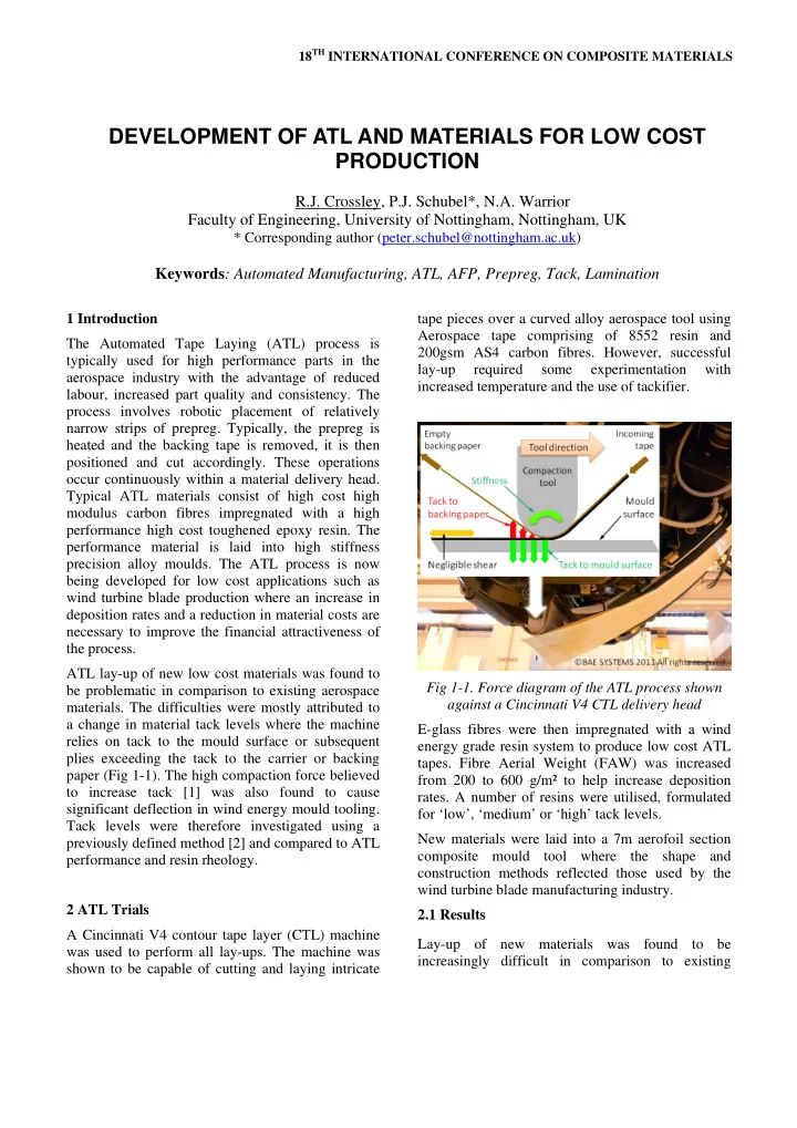
a change in material tack levels where the machine E-glass fibres were then impregnated with a wind relies on tack to the mould surface or subsequent energy grade resin system to produce low cost ATL plies exceeding the tack to the carrier or backing tapes. Fibre Aerial Weight (FAW) was increased paper (Fig 1-1). The high compaction force believed from 200 to 600 g/m² to help increase deposition to increase tack [1] was also found to cause rates. A number of resins were utilised, formulated significant deflection in wind energy mould tooling. for ‘low’, ‘medium’ or ‘high’ tack levels. Tack levels were therefore investigated using a New materials were laid into a 7m aerofoil section previously defined method [2] and compared to ATL composite mould tool where the shape and performance and resin rheology. construction methods reflected those used by the wind turbine blade manufacturing industry. 2 ATL Trials 2.1 Results A Cincinnati V4 contour tape layer (CTL) machine Lay-up of new materials was found to be was used to perform all lay-ups. The machine was increasingly difficult in comparison to existing shown to be capable of cutting and laying intricate

  2. aerospace ATL tape and attributed to three main manual handling capabilities appears to increase the problem areas; Cutting, release from the backing probability that manual intervention is required. paper and tack to the mould surface. The new materials were laid into low cost glass Cutting issues were attributed to a build up of resin epoxy moulds typical of those used in the turbine on the cutter tip (Fig 2-1) and were alleviated with a industry. The moulds were subsequently found to change in cutter blade geometry. Resin build up deflect under the high (265-1300N [3]) compaction continued with the new cutter although away from force of the tool head causing the ATL to halt due to the tip allowing cutting to continue. Lay-up was alignment issues. paused regularly to remove the resin build up preventing it from dropping off into the laminate. To Overall ATL was successfully used to produce a 7m reduce resin build up the resin content was limited to representative section of a 45m wind turbine blade 28% by weight. Cutter issues were not investigated (Fig 2-2). However, mould deflection and tolerance further as they were found to be alleviated issues limited each ply to 60-75% automated lay-up completely with the use of ultrasonic cutters with with the rest of the ply finished by hand. Further which the latest machines are equipped as standard. research is now required to avoid the use of tackifier and manual intervention due to lay-up failures resulting from inadequate tack to the mould surface or poor release from the backing paper, all of which were found to reduce the overall achievable deposition rate. Fig 2-1. Resin build up on the cutter tip found when using low cost ATL tape Poor lay-up performance was found when using ‘high’ and ‘medium’ tack resins attributed to poor release from the backing paper. Additionally, ATL Fig 2-2. ATL lay-up achieved over a curved 7m operators believe that manual intervention is always representative wind turbine blade mould tool required and found to be increasingly difficult as tack levels increase. Therefore, low tack resin 3 Tack testing & rheology systems were preferred. These low tack tapes were found to be difficult to lay-up due to poor adhesion 3.1 Method to the mould surface which became increasingly A newly developed peel test method, which difficult with the use of mould release agents. simulates the ATL process, was utilised to compare Subsequently, in-house tackifier was required to new ATL prepreg materials [2]. The prepreg is give adequate tack to the mould surface for pulled through rollers against a rigid substrate with a successful lay-up of the first ply. Poor mould compaction force applied. The covered prepreg is adhesion also increased the risk of the entire lay-up measured first which gives dynamic bending shifting in position or being lifted entirely from the stiffness. The test then moves continuously onto a mould surface during subsequent plies. Therefore, non covered section measuring peel resistance. the operators preference to low tack material for Dynamic stiffness is subtracted from the peel

  3. resistance to quantify the tack level (Fig 3-1). The effects of temperature, resin type, FAW, fibre type, compaction pressure and release agents were studied on tack and compared with the effect of temperature on the rheological dynamic storage modulus of resin only samples taken from the prepreg. Fig 3-2. Interfacial (left) and cohesive (right) failure modes found in E-glass ATL tape peel testing. Fig 3-1. Typical peel test results and analysis of medium tack ATL E-glass tape 3.2 Results & Discussion Both aerospace and new low cost e-glass ATL tapes showed a transition between two failure modes, distinguished by differences in resin deposition Fig 3-3. The tack and stiffness response of patterns and the formation of fibrils (Fig 3-2). The aerospace and low cost E-glass ATL tapes failure modes were consistent with pressure sensitive adhesives (PSA) peel [4] where failure at Two tapes of equal resin type and content by weight the surface with little resin deposition is termed were compared with alternative fibre types (Fig 3-4). ‘interfacial failure’. In contrast, failure within the The carbon fibre tape displayed consistently lower resin leading to significant resin deposition is known tack over a temperature range. The reduction in tack as ‘cohesive’. The failure modes are also consistent was attributed to a lower resin volume fraction due with those previously identified in ATL like to the lower density of carbon fibres resulting in a apparatus [5]. These failure modes are also change in impregnated resin distribution. However, associated with the viscoelasticity of the resin in the significant resin deposition continued to be observed PSAs viscoelastic windows principle [4]. at the plate surface. Therefore, other possibilities such as failure at the resin-fibre interface or an Despite the similarities in observed behaviour electrostatic effect [5, 6] could not be ruled out. between the two tapes, a significant difference in tack response was found (Fig 3-3). The tack of Three tapes of equal FAW and E-glass fibre type aerospace tape remained low with only a minor peak with alternative ‘high’, ‘medium’ and ‘low’ tack observed at the failure mode transition of around resin systems were also compared at ambient 55°C. Low cost E-glass tape revealed a significant temperature (Fig 3-5). The results showed good peak in tack around the failure mode transition agreement with suppliers specified tack levels with temperature of 27°C. little effect on prepreg dynamic stiffness. 3

Download Presentation
Download Policy: The content available on the website is offered to you 'AS IS' for your personal information and use only. It cannot be commercialized, licensed, or distributed on other websites without prior consent from the author. To download a presentation, simply click this link. If you encounter any difficulties during the download process, it's possible that the publisher has removed the file from their server.

Recommend


More recommend