
SLIDE 1
14/10/2019 1
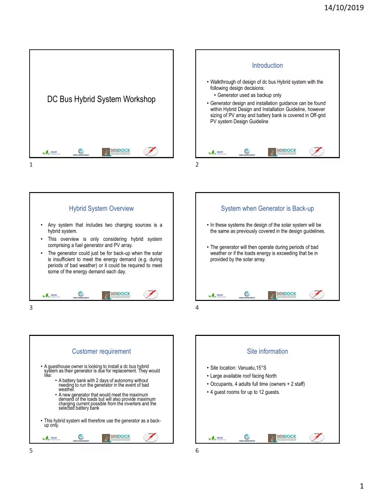
DC Bus Hybrid System Workshop
Introduction
- Walkthrough of design of dc bus Hybrid system with the
following design decisions:
- Generator used as backup only
- Generator design and installation guidance can be found
within Hybrid Design and Installation Guideline, however sizing of PV array and battery bank is covered in Off-grid PV system Design Guideline
Hybrid System Overview
- Any system that includes two charging sources is a
hybrid system.
- This overview is only considering hybrid system
comprising a fuel generator and PV array.
- The generator could just be for back-up when the solar
is insufficient to meet the energy demand (e.g. during periods of bad weather) or it could be required to meet some of the energy demand each day.
System when Generator is Back-up
- In these systems the design of the solar system will be
the same as previously covered in the design guidelines.
- The generator will then operate during periods of bad
weather or if the loads energy is exceeding that be in provided by the solar array.
Customer requirement
- A guesthouse owner is looking to install a dc bus hybrid
system as their generator is due for replacement. They would like:
- A battery bank with 2 days of autonomy without
needing to run the generator in the event of bad weather.
- A new generator that would meet the maximum
demand of the loads but will also provide maximum charging current possible from the inverters and the selected battery bank
- This hybrid system will therefore use the generator as a back-
up only.
Site information
- Site location: Vanuatu,15°S
- Large available roof facing North
- Occupants, 4 adults full time (owners + 2 staff)
- 4 guest rooms for up to 12 guests.