datasheet orbital anemometer
play

Datasheet Orbital Anemometer Module type ......................... - PDF document

Datasheet Orbital Anemometer Module type ......................... Cup Anemometer. Type nr. ............................... 420 Description........................... To be used in wind turbines for measuring the wind speed HW-version


  1. Datasheet Orbital Anemometer Module type ......................... Cup Anemometer. Type nr. ............................... 420 Description........................... To be used in wind turbines for measuring the wind speed HW-version ....................... 2.02 Documentation.......................... Anemometer420_2011 Calibration………………………. Measnet ORBITAL A/S Phone +45 97 35 24 22 E-mail orbital@orbital.dk Trykkerivej 5 DK 6900 Skjern Fax +45 97 35 32 85 Website www.orbital.dk

  2. 1 Contents 1 Contents ............................................................................................................................................................ 2 2 Features ............................................................................................................................................................ 3 2.1 Output frequency........................................................................................................................................ 3 3 Mounting the anemometer ................................................................................................................................ 3 3.1 Mechanically mounting............................................................................................................................... 3 3.2 Electrical mounting..................................................................................................................................... 3 4 Environmental data............................................................................................................................................ 4 4.1 Temperature............................................................................................................................................... 4 4.2 Windspeed ................................................................................................................................................. 4 5 Mechanical data ................................................................................................................................................ 4 5.1 Materials..................................................................................................................................................... 4 5.2 Cable .......................................................................................................................................................... 4 5.3 Screwed connection................................................................................................................................... 4 5.4 Weight ........................................................................................................................................................ 4 5.5 Transport container .................................................................................................................................... 4 6 Power supply..................................................................................................................................................... 5 6.1 Power supply.............................................................................................................................................. 5 7 Interface............................................................................................................................................................. 5 7.1 Output-signal & Power ............................................................................................................................... 5 8 Output................................................................................................................................................................ 5 8.1 Output-signal.............................................................................................................................................. 5 9 Calibration and test............................................................................................................................................ 5 9.1 Calibration .................................................................................................................................................. 5 10 Standards .......................................................................................................................................................... 6 10.1 EMC standards........................................................................................................................................... 6 11 Mechanical dimensions (principle drawing) ...................................................................................................... 7 Page......................:2

  3. 2 Features • Opto-electrical sensor • PNP output • Robust and Long-term durability performance (brass/stainless steel) • Prepared for heating unit 2.1 Output frequency Output : ..................................... : V [m/s] = 0,183 * f [Hz] + 0,65 V = wind speed [m/s] a = 0,183 *) b = 0,65 *) *) Approximate values. 3 Mounting the anemometer 3.1 Mechanically mounting Mounting vertically. (With enclosed M12 mounting bolt (Stainless steel)) Attention: Please follow the instructions above. Do NOT remove the anemometer cups from the shaft. Reduced lifetime and bad calibration will be the result. Mounting base must be connected to earth. 3.2 Electrical mounting Cable shield must be grounded, i.e. earth connected. Page......................:3

  4. 4 Environmental data 4.1 Temperature Operating temperature range .... : -20..+50° C Storage temperature range ....... : -40..+70° C 4.2 Windspeed Start wind speed........................ : 1,5 m/s
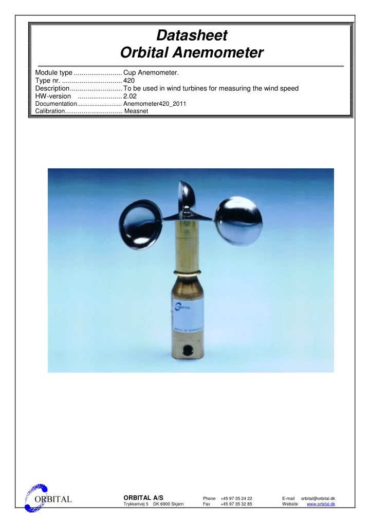
 5 Mechanical data 5.1 Materials Housing................................................: Brass (Cu Zn39Pb3) Top.......................................................: Stainless 18/8 Steel (Aisi 304) Bearings...............................................: Low friction precision steel bearings, on top semi-closed with special seal. 5.2 Cable Cable type............................................: Shielded PVC LIYCH, 3 x 0,25 mm 2 Cable diameter ....................................: 4,6 mm 5.3 Screwed connection Material ................................................: Stainless 18/8 Steel Type.....................................................: M12, 50.616M/EMV, (EMC) 5.4 Weight Weight..................................................: 0,75 kg 5.5 Transport container Dimensions (l x h x w)..........................: 278 x 185 x 217 mm Material ................................................: Expanded polystyrene Total weight .........................................: 1,15 kg Page......................:4

  5. 6 Power supply 6.1 Power supply Input voltage ............................. : 24VDC Input current.............................. : 0.05 A max 7 Interface 7.1 Output-signal & Power Interface standard................................: 3-wire shielded cable Cable Wire colour Function White +24 VDC (+) Brown Output-signal / High (18 V) – Low (floating) Green 0 VDC (-) (Black) Shield, (Is connected inside Anemometer) 8 Output 8.1 Output-signal Output type ..........................................: PNP Number of outputs ...............................: 1 Output load ..........................................: 0.03 A max 9 Calibration and test 9.1 Calibration The calibration is made by: “Svend Ole Hansen Aps” or “Force Technology” Copy of general calibration certificate will be forwarded on request. Separately calibrated anemometers can be delivered, with calibration report. Page......................:5

  6. 10 Standards 10.1 EMC standards DS/EN 50081-2:1994................ : Electromagnetic compatibility - Generic emission standard - Part 2: Industrial environment DS/EN 61000-6-2:1999 ........... : Electromagnetic compatibility (EMC) - Part 6-2: Generic standards – Immunity for industrial environment Page......................:6

  7. 11 Mechanical dimensions (principle drawing) Page......................:7

Download Presentation
Download Policy: The content available on the website is offered to you 'AS IS' for your personal information and use only. It cannot be commercialized, licensed, or distributed on other websites without prior consent from the author. To download a presentation, simply click this link. If you encounter any difficulties during the download process, it's possible that the publisher has removed the file from their server.

Recommend


More recommend