
SLIDE 1
CS/EE 5710/6710 Layout Basic Transistor Sizing Intro to Verilog - - PDF document
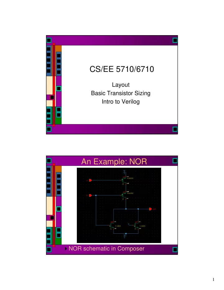
CS/EE 5710/6710 Layout Basic Transistor Sizing Intro to Verilog An Example: NOR NOR schematic in Composer 1 First Layout: Follow Schematic Note that layout of transistors follows the schematic Two P-types in series pulling up
initial begin a[1:0] = 2'b00; b[1:0] = 2'b00; cin = 1'b0; $display("Starting..."); #20 $display("A = %b, B = %b, c = %b, Sum = %b, Cout = %b", a, b, cin, sum, cout); if (sum != 00) $display("ERROR: Sum should be 00, is %b", sum); if (cout != 0) $display("ERROR: cout should be 0, is %b", cout); a = 2'b01; #20 $display("A = %b, B = %b, c = %b, Sum = %b, Cout = %b", a, b, cin, sum, cout); if (sum != 00) $display("ERROR: Sum should be 01, is %b", sum); if (cout != 0) $display("ERROR: cout should be 0, is %b", cout); b = 2'b01; #20 $display("A = %b, B = %b, c = %b, Sum = %b, Cout = %b", a, b, cin, sum, cout); if (sum != 00) $display("ERROR: Sum should be 10, is %b", sum); if (cout != 0) $display("ERROR: cout should be 0, is %b", cout); $display("...Done"); $finish; end
reg [1:0] ainarray [0:4]; // define memory arrays to hold input and result reg [1:0] binarray [0:4]; reg [2:0] resultsarray [0:4]; integer i; initial begin $readmemb("ain.txt", ainarray); // read values into arrays from files $readmemb("bin.txt", binarray); $readmemb("results.txt", resultsarray); a[1:0] = 2'b00; // initialize inputs b[1:0] = 2'b00; cin = 1'b0; $display("Starting..."); #10 $display("A = %b, B = %b, c = %b, Sum = %b, Cout = %b", a, b, cin, sum, cout); for (i=0; i<=4; i=i+1) // loop through all values in the memories begin a = ainarray[i]; // set the inputs from the memory arrays b = binarray[i]; #10 $display("A = %b, B = %b, c = %b, Sum = %b, Cout = %b", a, b, cin, sum, cout); if ({cout,sum} != resultsarray[i]) $display("Error: Sum should be %b, is %b instead", resultsarray[i],sum); // check results array end $display("...Done"); $finish; end