
The E-Class Body Structure
Arigid platform with these benefits:
- A solid platform for the suspension, contributing to superb handling!
- Mercedes-Benz patented passenger safety frame and crumple zones -
front and rear!
- An industty benchmark for durability and noise reduction!
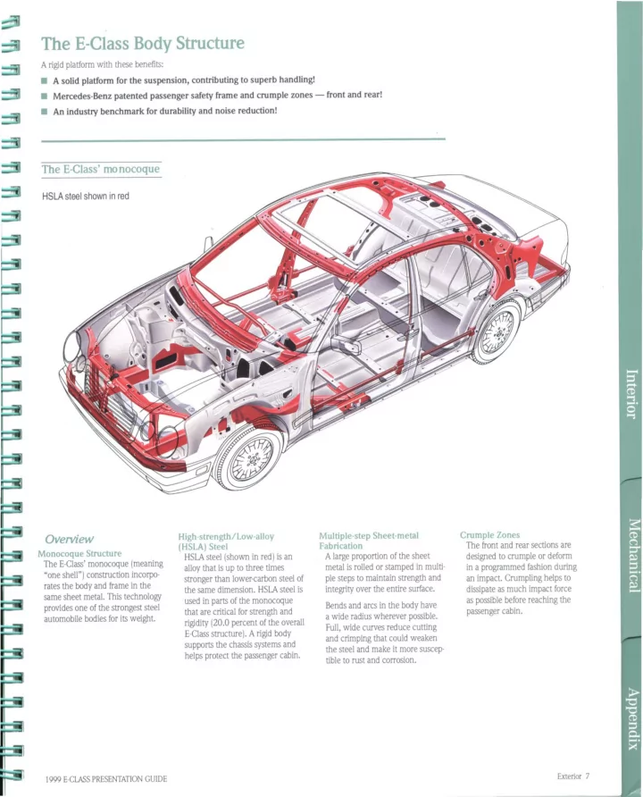
The E-Class' monocoque
HSLA steel shown in red
OVerview
Monocoque Structure The E-Class' monocoque (meaning "one shell") construction incorpo- rates the body and frame in the same sheet metal. This technology provides one of the strongest steel automobile bodies for its weight.
1999 E·CLASS PRESENTATION GUIDE
High-strength/Low-alloy (HSLA) Steel
HSLA steel (shown in red) is an alloy that is up to three times
stronger than lower-carbon steel of the same dimension. HSLA steel is used in parts of the monocoque that are critical for strength and rigidity (20.0 percent of the overall
E-Class structure). Arigid body supports the chassis systems and helps protect the passenger cabin. Multiple-step Sheet-metal Fabrication
Alarge proportion of the sheet metal is rolled or stamped in multi-
ple steps to maintain strength and integrity over the entire surface. Bends and arcs in the body have
a wide radius wherever possible.
Full, wide curves reduce cutting and crimping that could weaken the steel and make it more suscep- tible to rust and corrosion. Crumple Zones The front and rear sections are designed to crumple or deform in a programmed fashion during an impact. Crumpling helps to dissipate as much impact force as possible before reaching the passenger cabin.
Exterior 7