
SLIDE 1
CPSC 213
Introduction to Computer Systems
Unit 2a
I/O Devices, Interrupts and DMA
1Reading
- Text
- Exceptions, Logical Control Flow, Signal Terminology, Sending Signals,
Receiving Signals
- 8.1, 8.2.1, 8.5.1-8.5.3
Looking Beyond the CPU and Memory
- Memory Bus
- data/control path connecting CPU,
Main Memory, and I/O Bus
- I/O Bus
- data/control path connecting Memory
Bus and I/O Controllers
- e.g. PCI
- I/O Controller
- a processor running software
(firmware)
- connects I/O Device to I/O Bus
- e.g. SCSI, SATA, Ethernet, ...
- I/O Device
- I/O mechanism that generates or
consumes data
- e.g. disk, radio, keyboard, mouse, ...
CPU Memory
Memory Bus I/O Bus I/O Controllers I/O Devices
The Processors
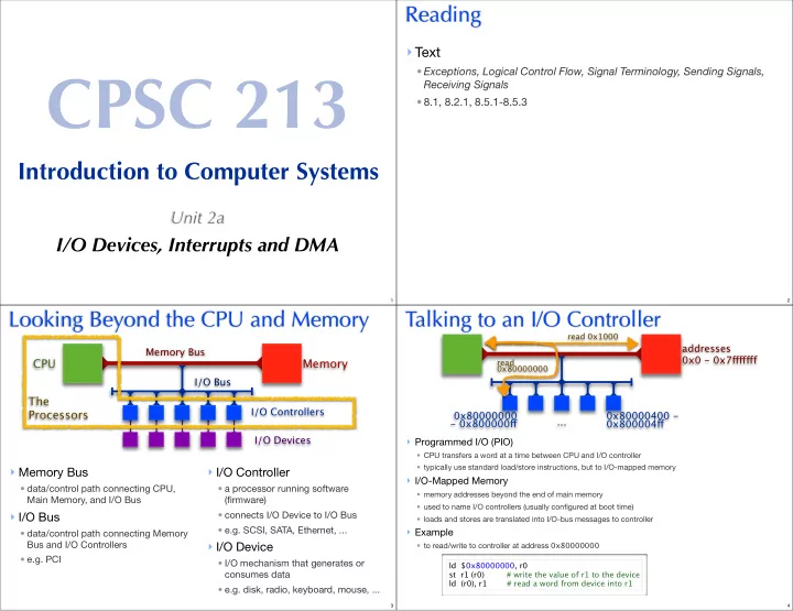
3Talking to an I/O Controller
- Programmed I/O (PIO)
- CPU transfers a word at a time between CPU and I/O controller
- typically use standard load/store instructions, but to I/O-mapped memory
- I/O-Mapped Memory
- memory addresses beyond the end of main memory
- used to name I/O controllers (usually configured at boot time)
- loads and stores are translated into I/O-bus messages to controller
- Example
- to read/write to controller at address 0x80000000
ld $0x80000000, r0 st r1 (r0) # write the value of r1 to the device ld (r0), r1 # read a word from device into r1
addresses 0x0 - 0x7fgfgfgf 0x80000000
- 0x800000fg
...
read 0x1000 read 0x80000000
0x80000400 - 0x800004fg
4