communication systems for vehicle electronics
play

Communication systems for vehicle electronics Presentation overview - PDF document

2014-05-05 Communication systems for vehicle electronics Communication systems for vehicle electronics Presentation overview Background automotive electronics as an application area for real-time communication Real time protocols LIN


  1. 2014-05-05 Communication systems for vehicle electronics Communication systems for vehicle electronics Presentation overview  Background automotive electronics as an application area for real-time communication  Real time protocols LIN – Local Interconnection Network CAN – Controller Area Network TTCAN , - Time Triggered CAN (based on “ Controller Area Network ” (CAN) CAN FD – CAN with Flexible Data-rate FlexRay , based on BMW ’ s “ ByteFlight ”  Hybrid scheduling 1 combining static scheduling with fixed priority scheduling analysis 1 Roger Johansson/2014 Communication systems for vehicle electronics 
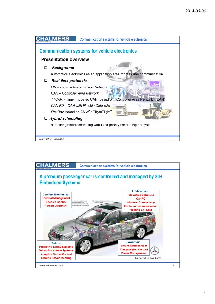
A premium passenger car is controlled and managed by 80+ Embedded Systems Infotainment: Comfort Electronics: Telematics Solutions Thermal Management Car PC Chassis Control Wireless Connectivity Parking Assistant Car-to-car communication Floating Car Data Powertrain: Safety: Engine Management Predictive Safety Systems Transmission Control 2 Driver Assistance Systems Power Management Adaptive Cruise Control Electric Power Steering Courtesy of Daimler, Bosch 2 Roger Johansson/2014 1

  2. 2014-05-05 Communication systems for vehicle electronics Virtual differentiation between variants Entertainment Variant 1 configuration A  All variants of a specific model are physically identical and differ only in Motor their individual software configuration A configuration  The various included Entertainment configuration F physical components can be activated or deactivated Motor by the software configuration B Variant 2 3 Roger Johansson/2014 Communication systems for vehicle electronics Example of the electrical system complexity 1927-1997 1200 � 1200 � 54 � 54 � No. of � No. of � meters of � meters of � No. of fuses � electric � electric � wires � wires � 27 � 27 � 575 � 575 � 16 � 16 � Wiring diagram, Volvo ÖV4 (“Jacob”) 1927 � 283 � 283 � 9 � 9 � 7 � 7 � 183 � 183 � 5 � 5 � 83 � 83 � 4 � 4 � 50 � 50 � 30 � 30 � 1927 � 1944 � 1956 � 1966 � 1975 � 1982 � 1982 � 1997 � 1927 � 1944 � 1956 � 1966 � 1975 � 1997 � 4 Roger Johansson/2014 2

  3. 2014-05-05 Communication systems for vehicle electronics The evolution of functional requirements on the electrical system Features Power production and distribution � 450 Architecture � Simple 400 Optimisation on many components � levels � 350 Standardised interfaces � 300 # of More complex functions � 250 functions stand-alone systems � 200 ABS, Airbag � 150 # of 100 Integration of systems � integrated functions 50 Optimisation of information � Common data busses � 0 1930 1940 1950 1960 1970 1980 1990 1995 2000 2005 1970 � 1980 � 1990 � 2000 � 2010 � 5 Roger Johansson/2014 Communication systems for vehicle electronics Automotive electronics roadmap 6 Roger Johansson/2014 3

  4. 2014-05-05 Communication systems for vehicle electronics Multiplex Networks Conventional � Network � Data 
 Identifier � Control � system � Command � Engine Control � Module � Driver Information � Control units � Automatic 
 Transmission � Central Module � 7 Roger Johansson/2014 Communication systems for vehicle electronics Evolution of protocols MOST Byteflight FlexRay CAN FD TTCAN TTP/C CAN CAN 2.0 VAN J1850 LIN 1990 1995 2000 2005 2010 1985 8 Roger Johansson/2014 4

  5. 2014-05-05 Communication systems for vehicle electronics Example of the electrical system… Mirror Lock Lock Window lift Power Train Seat Seat Heating Instruments Heating Central body control Infotainment Roof Roof systems Trunk Climate Heating Seat Seat Seat Seat Heating Steering wheel panel Interior lights Universal motor Lock Very high performance Lock Lock Lock Universal panel High performance Mirror Medium performance Mirror Low end performance 9 Roger Johansson/2014 Communication systems for vehicle electronics The LIN protocol, started in 1998 LIN Local Interconnection network predecessor: VOLCANO Lite Cooperation between partners: Freescale, VOLVO CAR, BMW, AUDI, Volkswagen, Daimler-Chrysler Mentor Graphics (former: Volcano Communication Technology) Objectives: Low cost, modest performance and safety requirements, flexible system architecture 10 Roger Johansson/2014 5

  6. 2014-05-05 Communication systems for vehicle electronics LIN target applications Steering Wheel: (very many controls are going to be Roof: positioned on the steering wheel) (high amount of wiring) Cruise Control, Wiper, Turning Light, … Rain Sensor, Light Sensor, Light Control, Sun Roof … Optional: Climate Control, Radio, (Rain Sensor needs to be Telephone, etc. interrogated every 10-20ms) Seat: many Seat Position Motors, Occupancy Sensor, Control Panel Door/window/seat: Mirror,Central ECU, Climate: Mirror, Switch, Window many Small Motors Lift, Control Panel Seat Control Switch, Door Lock, etc. 11 Roger Johansson/2014 Communication systems for vehicle electronics LIN protocol features – Bus topology – Master-slave protocol, no arbitration required – UART protocol, 10 bits (uses “sync break” facility) – 8 bits of data in a block – 2-8 blocks of data per frame – Single wire – Maximum 20 kbits/s 12 Roger Johansson/2014 6

  7. 2014-05-05 Communication systems for vehicle electronics LIN bus communication master control unit slave control unit slave control unit polling master task slave task slave task slave task inter-frame spacing synch next synch field Identifier field Master Task time 1 byte 2 byte block parity data Response spacing time Slave Task 13 Roger Johansson/2014 Communication systems for vehicle electronics CAN – Controller Area Network – Bus topology – CSMA/CR (Carrier sense, Multiple ARB Arbitration ( identifier ) Access/ Collision Resolution) CTRL Control information – Error detection capabilities DATA 0-8 bytes – Supports “atomic broadcast” CRC Checksum – 0-64 bytes of data per frame ACK Acknowledge EOF End of frame – Twisted pair – Maximum 1 Mbit/s MESSAGE FRAME SOF ARB CTRL DATA CRC ACK EOF 14 Roger Johansson/2014 7

  8. 2014-05-05 Communication systems for vehicle electronics Bus collission detection Bus transceivers ”Open collector” Bus level: Recessive (bit) ”1” Dominant (bit) ”0” Idle bus (recessive level) +5V R Bus level 1 1 Node A Node B 15 Roger Johansson/2014 Communication systems for vehicle electronics Bus arbitration Two nodes transmitting same level (1) transmit 1 receive 1 +5V transmit 1 I R = 0 receive 1 Bus level 1 1 1 1 1 1 I A = 0 I B = 0 A B Node Node 16 Roger Johansson/2014 8

  9. 2014-05-05 Communication systems for vehicle electronics Collission Resolution transmit 1 +5V receive 0 transmit 0 I R =I A R receive 0 Bus level: 0V Node A Node B 0 0 1 1 0 0 1 1 I A I B =0 Node B aborts transmission since the received bit differs from the transmitted bit 17 Roger Johansson/2014 Communication systems for vehicle electronics Three messages collide... Arbitration field (identifier with priority) Nodes ”own” specific message identifiers. EXAMPLE: Three nodes start simultaneously Node A transmits: $257 (0010 0101 0111) Node B transmits: $360 (0011 0110 0000) Node C transmits: $25F (0010 0101 1111) Bit number SOF 1 2 3 4 5 6 7 8 9 10 11 12 13 Bus level D D D R D D R D R D R R R R Node A 0 0 0 1 0 0 1 0 1 0 1 1 1 1 Node B 0 0 0 1 1 Aborts Node C 0 0 0 1 0 0 1 0 1 1 Aborts 18 Roger Johansson/2014 9

  10. 2014-05-05 Communication systems for vehicle electronics Standard/Extended CAN drawback.... – Protocol bus arbitration, acknowledge and error handling slow down bitrate ( maximum 1 Mbits/s) – Solution: New CAN FD specification CAN Flexible Data-rate 19 Roger Johansson/2014 Communication systems for vehicle electronics By-wire control Electronic information carrier Hydraulic information carrier The F-8 Digital Fly-By-Wire (DFBW) flight research project validated the principal concepts of all-electric flight control systems now used on nearly all modern high-performance aircraft and on military and civilian transports. The first flight of the 13-year project was on 20 May 25, 1972. Courtesy of Dryden Flight Research Center 20 Roger Johansson/2014 10

  11. 2014-05-05 Communication systems for vehicle electronics Control system implementation strategies Local control  Local information processing  Independent control objects Centralized global control  Local and central information processing  Interconnected control objects Distributed global control  Local and distributed information processing  Interconnected control objects 21 Roger Johansson/2014 Communication systems for vehicle electronics Non-functional requirements System life Maintainability time Extendability Interoperability Changeability Portability Safety Testability Restructuring Performance/ Usability Efficiency System Security Availability Architecture Robustness Cost-effectiveness Reliability Fault tolerance Produceability Understandability Timeliness Variability (variants, configurations) Conceptual integrity 22 Roger Johansson/2014 11

Download Presentation
Download Policy: The content available on the website is offered to you 'AS IS' for your personal information and use only. It cannot be commercialized, licensed, or distributed on other websites without prior consent from the author. To download a presentation, simply click this link. If you encounter any difficulties during the download process, it's possible that the publisher has removed the file from their server.

Recommend


More recommend