
SLIDE 1
1
bzalosh@firexplo.com OSHA Training Institute Dust Explosion Session 1
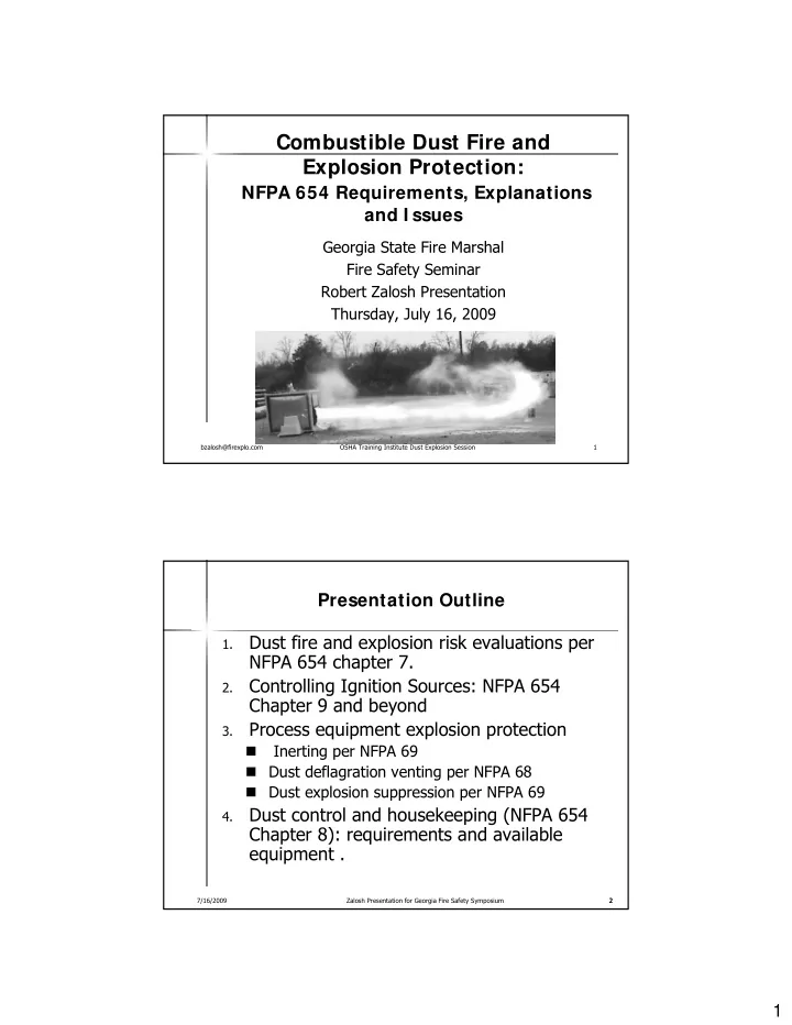
Combustible Dust Fire and Explosion Protection:
NFPA 654 Requirements, Explanations and I ssues
Georgia State Fire Marshal Fire Safety Seminar Robert Zalosh Presentation Thursday, July 16, 2009
7/16/2009 Zalosh Presentation for Georgia Fire Safety Symposium 2 2
Presentation Outline
1.
Dust fire and explosion risk evaluations per NFPA 654 chapter 7.
2.
Controlling Ignition Sources: NFPA 654 Chapter 9 and beyond
3.
Process equipment explosion protection
- Inerting per NFPA 69