
SLIDE 1
Collapsed Cone Convolution
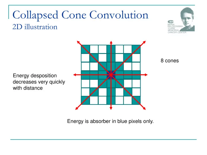
2D illustration
8 cones Energy is absorber in blue pixels only. Energy desposition decreases very quickly with distance
Collapsed Cone Convolution 2D illustration 8 cones Energy - - PowerPoint PPT Presentation
Collapsed Cone Convolution 2D illustration 8 cones Energy desposition decreases very quickly with distance Energy is absorber in blue pixels only. IGRT1 technologies Pawe Kukoowicz Warsaw, Poland IGRT The aim to ensure that the
2D illustration
8 cones Energy is absorber in blue pixels only. Energy desposition decreases very quickly with distance
Paweł Kukołowicz Warsaw, Poland
The aim
to ensure that the delivered dose distribution is
as close as possible to the planned dose distribution
to solve the problem of set-up uncertainties, to resist the changes of patient anatomy
during course of treatment,
to resist the changes of position of the target during single treatment session.
3/45
imaging
4/45
EPID
Cone beam CT
How does it go
the process of frequent two and three-dimensional imaging,
during a course of radiation treatment
adaptation the actual plan to the intendet one
5/45
EPID
Cone beam CT
How does it go
the process of frequent two and three-dimensional imaging,
during a course of radiation treatment
adaptation the actual plan to the intendet one
Construction
source of ionizing radiation detector
Systems
planar – 2D spatial – 3D
Ultrasound and laser systems are also
6/45
MV
therapetic beam is used
Compton effect very week contrast – no dependence on atomic number
▪
differences in radiological thickness only kV
additional source of radiation
a little photoelectric effect, but it is enough to have much better contrast – dependence on the atomic numer
▪
bones are visible very well
7 września 2012 Paweł Kukołowicz 7/45
Definition
2
/ _
1 2 1 2 P P P P
signal mean signal C
1-cm-thick bone embeded within 20 cm of soft tissue 100 kVp; contrast 0.5 6 MV; contrast 0.037
AAPM, Task Group 58
8/45
2
/ 2
1 2 1 2 S P P P P
noise signal SNR
Signal - to – noise - ratio AAPM, Task Group 58 100 kVp
6 MV 6 MV 6MV 6 MV
Patient dose (cGy)
0.05 0.05 1.00 10.00 55.00 SNR 71 <1 4.8 15 35
9/45
S dispersion signal mean SNR
EPIDs have changed radiotherapy
enoromusly
personally: IMRT and EPIDs are the most
important achievements in modern radiotherapy
IMRT
allows for safe treatment most of the concave targets
EPIDs
allows for safe treatment in general
10/45
What must be verified
mechanical and electrical safety
safety of mounting the EPID; risk of dropping the device on a patient (for
are expensive!)
geometrical reproducibility
the center of EPID should conform to the central axis
image quality
spatial and contrast resolution
software performance
11/45
Vendors usually recommends
some tests
Calibration should be made regularly
dark current or noise (image acquired without
beam)
uniformity of the image
for open field intensity across the beam should be uniform
12/45
Linearity
distortion of images
should be eliminated (simple phantoms with regularly placed objects)
Image quality
specialized phantoms are
used
Aluminium Las Vegas (AAPM)
PTW phantom
Las Vegas http://www.ws.aplus.pl/tomografia/EPID_image_quality.pdf
13/45
Image quality may be improved with
channging window and level more sophisticated digital filtering techniques for edge detection of bones
high pass filter Canny and Sobel
How we recognize objects?
www.cse.unr.edu/~bebis/CS791E/Notes/EdgeDetection.pdf
14/45
Recognition is driven by edges!
15/45
16/26
Leszek Chmielewski Przetwarzanie obrazów (medycznych)
... w rozpoznawaniu najważniejsze są krawędzie
Edge is a second derivative of intensity. MV image problem of noise!
17/45
kV radiation
The idea and first solution. Haynes Radiation
18/45
19/45
1 MU – 3 MU
A set of 2D images 3D image
Computerized tomography
conventional (on rails) tomograph
cone beam tomograph
MV cone beam CT
20/45
Difference between the fan (narrow) beam and cone-beam tomography. << 1 sec ~ 1 min
cone fan
SNR SNR
21/45
With kilovoltage
radiation
Elekta – Varian - On
Board Imaging
Specialized
software for image registration
Rtg lamp Detector - EPID
22/45
Worse than for conventional CT
smaller SNR
Good enough for soft tissue registration
in some clinical situations
distortions due to patient movement
1 min scan
Amer, et al. The British Journal of Radiology, 80 (2007), 476–482
23/45
treatment beam
24/45
25/45
kV radiation
The idea and first solution. Haynes Radiation Exact Track BrainLab CyberKnife
26/45
27/45
The only dose quantity that allows any intercomparison
scenarios … is effective dose, which combines the quality and distribution of radiation throughout the body with its effect on a number of specific organs.
If 10,000 individuals received 0.01 Sv each over background
during their life, 4 additional deaths would occur of the 2,000 that would naturally occur; (0.01 Sv – 1 cGy)
The management of imaging dose during image-guided radiotherapy: Report of the AAPM Task Group 75, Medical Physics 34, Oct, 2007
wT= tissue weighting factor wR= radiation weighting coefficient DT,R= average absorbed dose to tissue T
28/45
T R T R T
,
for radiation used in conventional radiotherapy wR = 1
29/45
Organ/Tissue WT Organ/Tissue WT Bone marrow 0.12 Lung 0.12 Bladder 0.04 Liver 0.04 Bone Surface 0.01 Oesophagus 0.04 Brain 0.01 Salivary glands 0.01 Breast 0.12 Skin 0.01 Colon 0.12 Stomach 0.12 Gonads 0.08 Thyroid 0.04 Liver 0.05 Remainder 0.12
For photons and electrons WR = 1
30/45
Murphy, M.J., et al., The management of imaging dose during image- guided radiotherapy: report of the AAPM Task Group 75. Med Phys,
Dose from Elekta XVI kV cone-beam CT.
31/45
required in verification of the target volume in radiotherapy,” Br. J. Radiol. 77, 557–561 2004.
Effective dose from 6 MV portal images 18 cm x 15.6 cm taken at SSD=88 cm. X2
32/45
5 cGy 6 cGy 4 cGy
Irradiation of rectum patient 8 MU protocol
In practice for MVCBCT we use about 4 MU.
Disadvantages in comparison to kV
low contras little higher unwanted dose
Advantages in comparison to kV
in 3D treatment fields might be imaged lower purchase cost lower running costs allow for imaging the H-Z objects
33/45
H-Z materials
34/45
7 września 2012 Paweł Kukołowicz 35/45
Alloy Co-Cr-Mo Titanium Steel
Atomic composition
Co 60% Cr 30% Mo 5% Ti 90% Al 6% Va 4% Fe 65% Cr 18% Ni 12 Mo 3
ρ
[g/cm3]
7.9 4.3 8.1
relative electron composition
6.8 3.6 6.7
36/45
water Titanium Steel μ/ρ [cm2/g]
0.0397 0.0351 0.0362
ρ [g/cm3]
1.0 4.3 8.1
attenuation for 1cm [%]
3.9 14.0 25.4
Is difficult and possible with metal artifaction
reduction method only
37/45
without MAR with MAR
can’t be imaged
with kV radiation
can be imaged
with MV radiation
38/45
Those who have Tomotherapy are lucky!
Always with MAR
module
With extended
mode
16 bits
up to 216; 65536 HU
12 bits (standard)
up to 212; 4096 HU: -1204 - +3071 (aluminium)
39/45
HU – electron density conversion curve
40/45
To be accounted for in total dose delivered to
a patient?
different policies
My opinion: in general there is no reason to
take into account the CBCT concomitant dose unless CBCT is performed each fraction
on-line protocol
41/45
The modern radiotherapy is imaged based
CT information for planning
fusion with other modalities
Several solutions
visualizing high contrast objects
bones
gold markers
visualizing low contarst objects
soft tissue
42/45
Several solutions
pre-irradiation information (low frequency)
inter-fraction changes
continuous (high frequency)
Intra-fraction changes
There are also other very sophisticated solutions
very expensive
43/45
Good news!
in more than 80% of cases (my estimation)
conventional portal control with EPID is enough,
IF The right proctocols are used, and applied
properly
the sructure, organization and personel are the most
important!
44/45
Thank you very much for your attention! Paweł Kukołowicz, p.kukolowicz@zfm.coi.pl
45/45