capacitors and inductors
play

Capacitors and inductors ENGR 40M lecture notes July 21, 2017 - PDF document

Capacitors and inductors ENGR 40M lecture notes July 21, 2017 Chuan-Zheng Lee, Stanford University Unlike the components weve studied so far, in capacitors and inductors , the relationship between current and voltage doesnt depend only on


  1. Capacitors and inductors ENGR 40M lecture notes — July 21, 2017 Chuan-Zheng Lee, Stanford University Unlike the components we’ve studied so far, in capacitors and inductors , the relationship between current and voltage doesn’t depend only on the present. Capacitors and inductors store electrical energy—capacitors in an electric field, inductors in a magnetic field. This enables a wealth of new applications, which we’ll see in coming weeks.
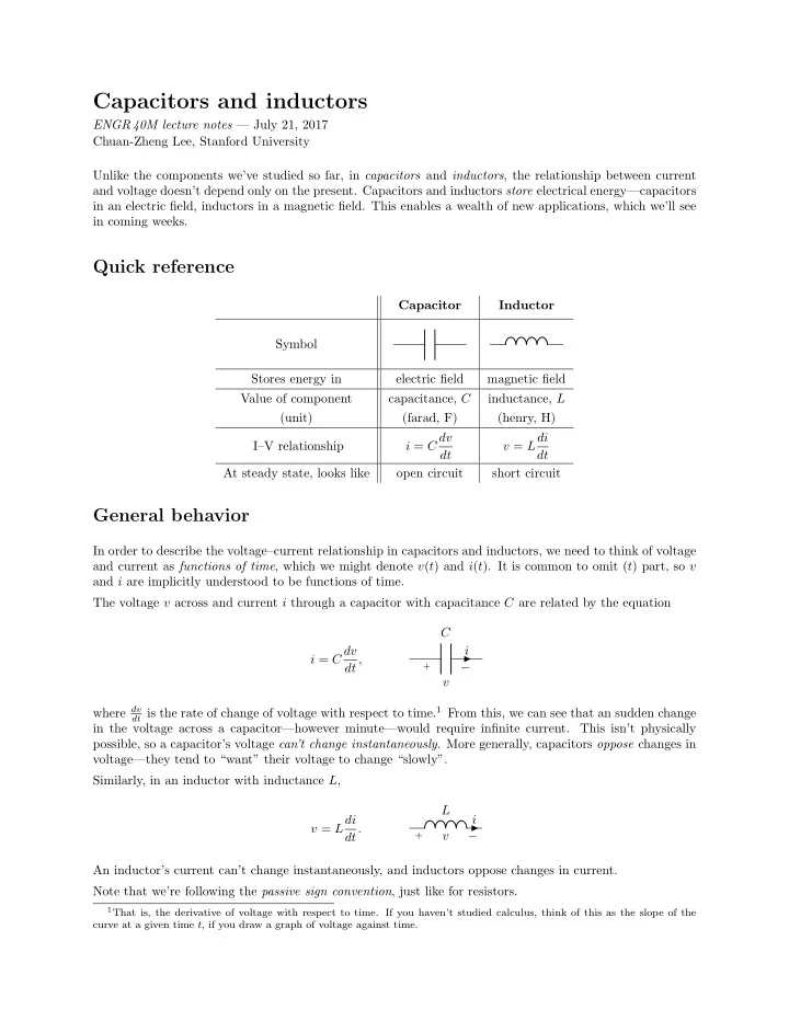
 Quick reference Capacitor Inductor Symbol Stores energy in electric field magnetic field Value of component capacitance, C inductance, L (unit) (farad, F) (henry, H) i = C dv v = Ldi I–V relationship dt dt At steady state, looks like open circuit short circuit General behavior In order to describe the voltage–current relationship in capacitors and inductors, we need to think of voltage and current as functions of time , which we might denote v ( t ) and i ( t ). It is common to omit ( t ) part, so v and i are implicitly understood to be functions of time. The voltage v across and current i through a capacitor with capacitance C are related by the equation C i = C dv i dt , + − v dt is the rate of change of voltage with respect to time. 1 From this, we can see that an sudden change where dv in the voltage across a capacitor—however minute—would require infinite current. This isn’t physically possible, so a capacitor’s voltage can’t change instantaneously . More generally, capacitors oppose changes in voltage—they tend to “want” their voltage to change “slowly”. Similarly, in an inductor with inductance L , L v = Ldi i dt. v + − An inductor’s current can’t change instantaneously, and inductors oppose changes in current. Note that we’re following the passive sign convention , just like for resistors. 1 That is, the derivative of voltage with respect to time. If you haven’t studied calculus, think of this as the slope of the curve at a given time t , if you draw a graph of voltage against time.

  2. Combinations in series and parallel Inductors combine similarly to resistors: L 1 L 1 L 2 L 2 � 1 � − 1 + 1 L 1 L 2 L s = L 1 + L 2 L p = = L 1 + L 2 L 1 L 2 Capacitors, however, are the other way round: C 1 C 1 C 2 C 2 � 1 � − 1 + 1 C 1 C 2 C s = = C 1 C 2 C 1 + C 2 C p = C 1 + C 2 Steady state analysis Steady state refers to the condition where voltage and current are no longer changing. Most circuits, left undisturbed for sufficiently long, eventually settle into a steady state. In a circuit that is in steady state, dv dt = 0 and di dt = 0 for all voltages and currents in the circuit—including those of capacitors and inductors. Thus, at steady state, in a capacitor, i = C dv dt = 0, and in an inductor, v = L di dt = 0. That is, in steady state, capacitors look like open circuits , and inductors look like short circuits , regardless of their capacitance or inductance. in steady state, looks like in steady state, looks like (This might seem trivial now, but we’ll use this fact repeatedly in more complex situations later.) Practical matters Manufacturers typically specify a voltage rating for capacitors, which is the maximum voltage that is safe to put across the capacitor. Exceeding this can break down the dielectric in the + capacitor. Capacitors are not, by nature, polarized : it doesn’t normally matter which way round you − connect them. However, some capacitors are polarized—in particular, electrolytic capacitors, where the insulator is a very thin oxide layer that would be depleted if a negative voltage is polarized applied. In schematics, if a capacitor is polarized, we use a special symbol for it, as shown capacitor right. 2

  3. Examples Example 1. In the (contrived) circuit below, at t = 0, the voltage across the capacitor is 0 V. The switch begins on the lower throw, moves to the upper throw at t = 0 ms, then moves back to the lower throw at t = 1 ms. Draw a graph of the voltage across the capacitor as a function of time. 1 mA 250 nF Example 2. In the (contrived) circuit below, at t = 0 ms, v a = 10 V. The switch begins on the lower throw, and moves to the upper throw at t = 0 ms. When does the capacitor’s voltage to reach 0 V? v a 500 ➭ A 2 ➭ F Example 3. You wish to replace the following network of capacitors with a single capacitor. What should its value be? 300 nF 600 nF 350 nF 150 nF Example 4. In the (contrived) circuit below, at t = 0, the current through the inductor is 100 mA upwards . The switch begins on the lower throw, moves to the upper throw at t = 0 ms, then moves back to the lower throw at t = 1 ms. Draw a graph of the current through the inductor i L , with reference direction going downwards , as a function of time. + 2 . 7 V 10 mH − i L 3

  4. Example 5. Find the total inductance of this inductor network. 15 ➭ H 15 ➭ H 50 ➭ H 45 ➭ H Example 6. The circuit below has reached steady state. What is the voltage v x ? 4 kΩ + v x 3 V − 2 . 7 nF 8 kΩ Example 7. The circuit below has reached steady state. (a) What is the voltage v x ? (b) What is the voltage across the capacitor? (Be sure to specify the direction.) 33 nF v x + 680 Ω 120 kΩ 6 V − Example 8. The circuit below has reached steady state. What is the voltage v x ? 4 nH 3 . 3 nF 10 kΩ 1 mH + v x 5 V − 2 . 7 nF 15 kΩ 4

Download Presentation
Download Policy: The content available on the website is offered to you 'AS IS' for your personal information and use only. It cannot be commercialized, licensed, or distributed on other websites without prior consent from the author. To download a presentation, simply click this link. If you encounter any difficulties during the download process, it's possible that the publisher has removed the file from their server.

Recommend


More recommend