
SLIDE 1
Physics 115
General Physics II Session 34
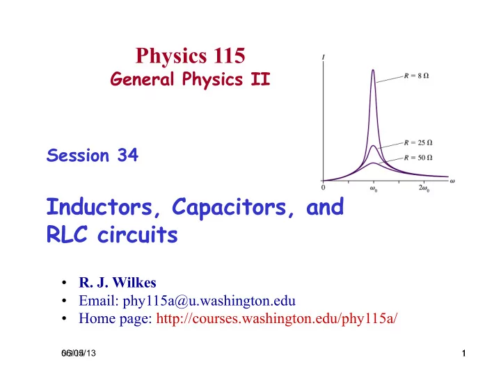
Inductors, Capacitors, and RLC circuits
06/05/13 1
- R. J. Wilkes
- Email: phy115a@u.washington.edu
- Home page: http://courses.washington.edu/phy115a/
6/3/14 1