brdf brdf computer graphics spring 2008 computer graphics
play

BRDF BRDF Computer Graphics (Spring 2008) Computer Graphics - PDF document

BRDF BRDF Computer Graphics (Spring 2008) Computer Graphics (Spring 2008) Reflected Radiance proportional to Irradiance Constant proportionality: BRDF [CW pp 28,29] COMS 4160, Lecture 20: Illumination and Shading 2 Ratio of outgoing


  1. BRDF BRDF Computer Graphics (Spring 2008) Computer Graphics (Spring 2008) � Reflected Radiance proportional to Irradiance � Constant proportionality: BRDF [CW pp 28,29] COMS 4160, Lecture 20: Illumination and Shading 2 � Ratio of outgoing light (radiance) to incoming light (irradiance) � Bidirectional Reflection Distribution Function http://www.cs.columbia.edu/~cs4160
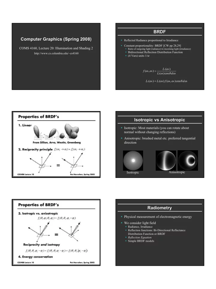
 � (4 Vars) units 1/sr ω L ( ) r r ω ω = f ( , ) i r ω θ ω L ( )cos d i i i i ω = ω ω ω θ ω L ( ) L ( ) ( f , )cos d r r i i i r i i Isotropic vs Isotropic vs Anisotropic Anisotropic � Isotropic: Most materials (you can rotate about normal without changing reflections) � Anisotropic: brushed metal etc. preferred tangential direction Anisotropic Isotropic Radiometry Radiometry � Physical measurement of electromagnetic energy � We consider light field � Radiance, Irradiance � Reflection functions: Bi-Directional Reflectance Distribution Function or BRDF � Reflection Equation � Simple BRDF models

  2. Reflection Equation Reflection Equation ω ω ω ω i i r r Sum over all light sources = ∑ ω ω ω ω ω ω = ω ω ω ω L ( ) L ( ) ( f , )( i n ) L ( ) L ( ) ( f , )( i n ) r r i i i r i r r i i i r i i Reflected Radiance Incident BRDF Cosine of Reflected Radiance Incident BRDF Cosine of (Output Image) radiance (from Incident angle (Output Image) radiance (from Incident angle light source) light source) Reflection Equation Radiometry Radiometry � Physical measurement of electromagnetic energy � We consider light field � Radiance, Irradiance ω d ω � Reflection functions: Bi-Directional Reflectance ω i i r Distribution Function or BRDF � Reflection Equation � Simple BRDF models = ∫ Replace sum with integral ω ω ω ω ω ω L ( ) L ( ) ( f , )( i n d ) r r i i i r i i Ω Reflected Radiance Incident BRDF Cosine of radiance (from Incident angle (Output Image) light source) Brdf Brdf Viewer plots Viewer plots Demo Demo Diffuse Torrance-Sparrow Anisotropic bv written by Szymon Rusinkiewicz

  3. Analytical BRDF: TS example Analytical BRDF: TS example Torrance- Torrance -Sparrow Sparrow � One famous analytically derived BRDF is the � Assume the surface is made up grooves at the microscopic level. Torrance-Sparrow model. � T-S is used to model specular surface, like the Phong model. � more accurate than Phong � Assume the faces of these grooves (called microfacets) are � has more parameters that can be set to match different perfect reflectors. materials � Take into account 3 phenomena � derived based on assumptions of underlying geometry. (instead of ‘because it works well’) Masking Interreflection Shadowing

  4. Torrance- -Sparrow Result Sparrow Result Other BRDF models Torrance Other BRDF models Geometric Attenuation: Fresnel term: reduces the output based on the allows for wavelength amount of shadowing or masking dependency � Empirical: Measure and build a 4D table that occurs. � Anisotropic models for hair, brushed steel Distribution: θ ω ω θ F ( ) ( G , ) D ( ) distribution function i i r h = f � Cartoon shaders, funky BRDFs determines what θ θ 4cos( )cos( ) i r percentage of microfacets are � Capturing spatial variation How much of the oriented to reflect in macroscopic surface How much of the the viewer direction. � Very active area of research is visible to the light macroscopic source surface is visible to the viewer Complex Lighting Complex Lighting Environment Maps Environment Maps � Instead of determining the lighting direction by knowing � So far we’ve looked at simple, discrete light sources. what lights exist, determine what light exists by knowing the lighting direction. � Real environments contribute many colors of light from many directions. � The complex lighting of a scene can be captured in an Environment map. � Just paint the environment on a sphere. Blinn and Newell 1976, Miller and Hoffman, 1984 Later, Greene 86, Cabral et al. 87 Demo Conclusion Conclusion Demo � All this (OpenGL, physically based) are local illumination and shading models � Good lighting, BRDFs produce convincing results � Matrix movies, modern realistic computer graphics � Do not consider global effects like shadows, interreflections (from one surface on another) � Subject of next unit (global illumination)

  5. What’ ’s Next s Next What � Have finished basic material for class � Review of illumination and Shading � Remaining topics are global illumination (written assignment 2): Lectures on rendering eq, radiosity � Historical movie: Story of Computer Graphics � Likely to finish these by April 21: No class April 28, � Work instead on HW 4, written assignments � May 5 will be demo session for HW 4

Download Presentation
Download Policy: The content available on the website is offered to you 'AS IS' for your personal information and use only. It cannot be commercialized, licensed, or distributed on other websites without prior consent from the author. To download a presentation, simply click this link. If you encounter any difficulties during the download process, it's possible that the publisher has removed the file from their server.

Recommend


More recommend