
SLIDE 1
The Modern CAD/CAM Workflow:
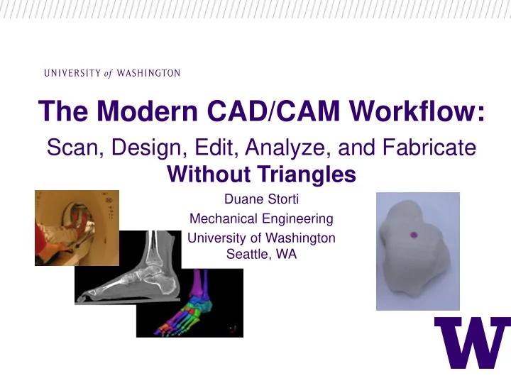
Scan, Design, Edit, Analyze, and Fabricate Without Triangles
Duane Storti Mechanical Engineering University of Washington Seattle, WA
Big picture context: Technology democratization Ubiquity of 3D - - PowerPoint PPT Presentation
The Modern CAD/CAM Workflow: Scan, Design, Edit, Analyze, and Fabricate Without Triangles Duane Storti Mechanical Engineering University of Washington Seattle, WA Big picture context: Technology democratization Ubiquity of 3D imaging
Duane Storti Mechanical Engineering University of Washington Seattle, WA
Coordinates F-rep Sphere SDF-rep Sphere Cartesian x2 + y 2 + z 2 – R2 < 0 𝑦2 + 𝑧2 + 𝑨2 – R < 0 Spherical r 2 – R2 < 0 r – R < 0
[1] Yurtoglu, M., GPU-based Parallel Computation of Integral Properties of Volumetrically Digitized Objects, PhD Dissertation, University of Washington, 2017. [2] Peterson, G., Schwartz, J., Zhang, D., Weiss, B., Ganter,M., Storti, D. and Boydston, AJ. Production of Materials with Spatially-Controlled Crosslink Density via Vat Photopolymerization, ACS Applied Materials & Interfaces. 8, 29037−29043 (2016). DOI:10.1021/acsami.6b09768 [3] Zhang, D., A GPU Accelerated Signed Distance Voxel Modeling System, PhD Dissertation, University of Washington, 2016. [4] Storti, D, and Yurtoglu, M., CUDA for Engineers: An Introduction to High-Performance Parallel Computing, Addison-Wesley Professional, NY, 2015. [5] Storti D, Ganter MA, Ledoux WR, Ching RP, Hu Y, Haynor D. Wavelet SDF-Reps: Solid Modeling With Volumetric Scans. ASME. International Design Engineering Technical Conferences and Computers and Information in Engineering Conference, Volume 6: 33rd Design Automation Conference, Parts A and B (2007):501-513. doi:10.1115/DETC2007-34703. [6] Storti, D., Ganter, M., Ledoux, W., Ching, R., Hu, Y., and Haynor, D. Artifact vs. Anatomy: Dealing With Conflict of Geometric Modeling Descriptions. No. 2007-01-2450. SAE Technical Paper, (2007). [7] Mark T. Ensz, Duane W. Storti, and Mark A. Ganter, Implicit Methods for Geometry Creation, Int. J.
DOI: http://dx.doi.org/10.1142/S0218195998000266