
SLIDE 1
AUTONOMOUS UNDERWATER VEHICLE CHARGING Advisors: Peng Zhang, Taofeek - - PowerPoint PPT Presentation
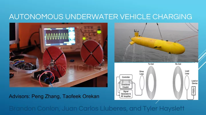
AUTONOMOUS UNDERWATER VEHICLE CHARGING Advisors: Peng Zhang, Taofeek Orekan Brandon Conlon, Juan Carlos Lluberes, and Tyler Hayslett SUMMARY Our section of the wave power team will focus on wireless power transfer (WPT) through seawater.
For Vin = 20V @ 100 kHz, K = 1, R = 1 Ω, C = 10.5 nF, L = 24 µH
Side view of example rig.