seabiscuit
play

Seabiscuit The 2009 University of Bath Autonomous Underwater - PowerPoint PPT Presentation

Seabiscuit The 2009 University of Bath Autonomous Underwater Vehicle Student Autonomous Underwater Challenge Europe July 2009 Summer Sea Trials Pacific Coast, BC, Canada July-October 2009 Benjamin Williamson, Sarah-Jane Bailey, Thomas


  1. Seabiscuit The 2009 University of Bath Autonomous Underwater Vehicle Student Autonomous Underwater Challenge Europe July 2009 Summer Sea Trials – Pacific Coast, BC, Canada July-October 2009 Benjamin Williamson, Sarah-Jane Bailey, Thomas Ruckser, Andrew Webster, William Megill, Martin Balchin, Stephen Dolan
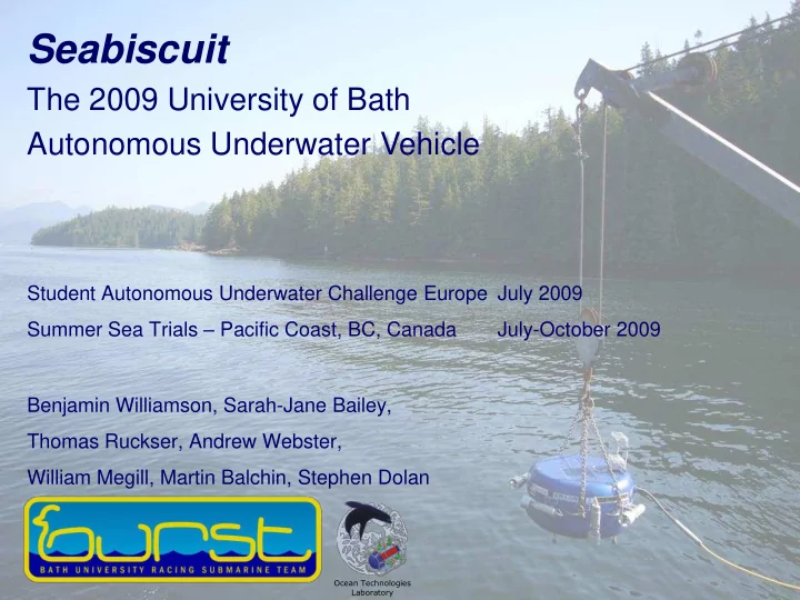
 Ocean Technologies Laboratory

  2. Design Evolution

  3. Design Evolution

  4. Mechanical Design  Hydrodynamic fibreglass shell  Aluminium frame supports dual pressure vessels and peripherals  Student designed, student built in-house

  5. Mechanical Design: Pressure Vessels  Reliability and ease of access

  6. Seabiscuit

  7. Motor housings  Built in-house  Materials  Blind bore  One O-ring  Double lip seal  Bilge  Pressure gradient  Oil filled  Tapered housing  Efficiency

  8. Holonomic Propulsion 6 fixed thrusters  70W Maxon motors  Holonomic movement in  the horizontal plane Benefits to sensing,  mapping and station- holding Holonomic control  Benefits of inertial  navigation Electrical power  24V SLA battery pack  Reversible PWM motor  controllers Auto-tuning PID  Controller

  9. Design Brief Student Autonomous Underwater Challenge – Europe (SAUC-E)  DSTL and Industry sponsored competition  Held in Portsmouth, UK  Submarine test tank (120m*60m*6m deep)  Designed to advance the field of AUVs  Foster the development of new ideas and techniques 

  10. SAUC-E Competition Competition tasks designed to simulate  real life tasks and challenges facing AUVs, including: Searching & identifying objects in the mid-  water and on the floor Passing through gates, navigating confined  passages Sonar and visual surveys  Mapping the environment and object location  Tracking moving targets  Autonomous docking into 1*1m docking bay 

  11. Background  Multi-purpose:  SAUC-E Competition  Canada Field Trials

  12. Background  Grey whale conservation

  13. Sensing  Vision (dual cameras)  Sonar (dual sonars)  Mapping  Inertial Measurement Unit, Pressure, Compass  6-axis INS to benefit holonomic movement  Machine health  Battery status (voltage, current, SoC)  Motor current consumption  Temperature  Internal pressure  Humidity & leak detection

  14. Buoy Bottom Target Bottom Target Colour Shape Tracking Send Information to AI

  15. Gate Finder

  16. Sonar - Image Processing  360˚ Sonar – Horizontal Plane  120˚ Sonar – Vertical Plane  Image analysis through LabVIEW

  17. Sonar - Image Processing Locating a corner

  18. Sonar - Image Processing Locating a corner

  19. Sonar - Image Processing Locating a corner

  20. Sonar - Image Processing Locating a corner

  21. Sonar - Image Processing Locating a corner

  22. Sonar - Image Processing Locating a corner

  23. Sonar - Mapping  The same principle applies to wall detection  Gathered information can be used for mapping

  24. Sonar - Identifying Objects OBJECT FILTERS - Nearest Neighbour If a particle has ONE close neighbour then the program classifies the two particles as one object. If a particle has TWO close neighbours then the program classifies the particle as noise.

  25. Sonar - Identifying Objects Right: Survey area, the piling dock and shoreline Below: Forward-facing profiling sonar of repeated dock pilings 360 ° Sonar Scan of Dock Pilings

  26. Sonar - Object Tracking Two key parameters are used to track objects from one frame to the next; particle location and area. The framework used for the tracking part of the program is shown below:

  27. Sensor Fusion & Mission Planning Sonar Navigation Sensors • 360 ° Scanning Sonar • DeltaT Profiling Sonar • 6 DoF Inertial Measurement Unit • 3 DoF Magnetometer • Gimballed Compass Vision Environmental sensors • Forward camera • Downward camera • Depth Pinger • Water Pressure Sensor Overall position estimate

  28. Sensor Fusion  Combines positional estimates from a variety of sensors , each with different characteristics  e.g. update frequency, noise, accuracy, etc.  Each sensors positional estimate is assigned a reliability estimate;  this determines its weighting (influence) on the overall positional estimate when combining conflicting data.  As environmental conditions change, the weightings are adjusted, e.g.:  turbid water (murky so lower weighting of vision)  turbulent water (increased sonar noise)  magnetic disturbances (reduced magnetometer accuracy)  Provides an overall position estimate and accuracy estimate

  29. Program Structure  Hierarchical Program  Overall mission plan runs subtasks  Allows for mission variation, either for competition or for difference ocean tasks  Artificial Intelligence  React to unforeseen circumstances – e.g. object found / not found, allows mission to continue

  30. Flexible program structure - Control as ROV (fly by wire)

  31. Future Design  Sensor fusion  Navigation in the near-shore environment  Station keeping in unsteady flows  Mechanical design for deepwater operation

  32. Sponsors & Acknowledgements

  33. To get involved...  SAUC-E Competition – July 2010  Canadian Field Trials – July-October 2010  Come and visit the lab  4 East 1.24  Email  b.j.williamson@bath.ac.uk

Download Presentation
Download Policy: The content available on the website is offered to you 'AS IS' for your personal information and use only. It cannot be commercialized, licensed, or distributed on other websites without prior consent from the author. To download a presentation, simply click this link. If you encounter any difficulties during the download process, it's possible that the publisher has removed the file from their server.

Recommend


More recommend