
SLIDE 1
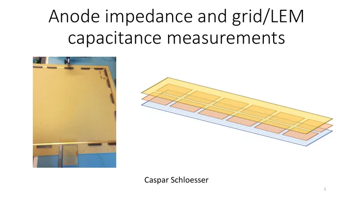
Anode impedance and grid/LEM capacitance measurements
Caspar Schloesser
1
Anode impedance and grid/LEM capacitance measurements Caspar - - PowerPoint PPT Presentation
Anode impedance and grid/LEM capacitance measurements Caspar Schloesser 1 Summary Impedance measurements 6x6x6 and 3x1x1 anodes Different connectors and KEL cable LEM-grid capacitance measurements For different LAr levels and
Caspar Schloesser
1
2
strip connection and the ground of the anode
3
Network analyzer
Anodes linked with PCB connector
Probe
4
probe, only the impedance of the 50 Ω cable is measured
goes to ∞ 50 Ω cable
5
50 Ω cable End of strips
strips of both anode modules
slightly different lengths → slightly different durations for signals to traverse entire copper track
6
have slightly different lengths → slightly different durations for signals to traverse entire copper track Edge strip
7
1.6 ns 2.2 ns 2.7 ns 4.0 ns PCB Kapton FEP KEL
Kapton connector
cables 12.25 ns
8
Taken from Pin-Jung Chiu
9
PCB Kapton FEP KEL PCB Kapton FEP KEL
10
Impedance matched within 15 Ω
within 15 Ω
connecting anode to SGFT flange
11
LCR meter LEM HV connections Grid LEMs Anode
12
Capacitance LEM down / grid Average: 193.75 pF Capacitance LEM up / grid Average: 168.5 pF
13
Capacitance LEM down / grid Average: 235.25 pF Capacitance LEM up / grid Average: 204.33 pF
14
Capacitance LEM down / grid Average: 169.08 pF Capacitance LEM up / grid Average: 146.25 pF
15
Capacitance LEM down / grid Average: 165.75 pF Capacitance LEM up / grid Average: 142.92 pF
16
Capacitance LEM down / grid Average: 223.92 pF Capacitance LEM up / grid Average: 193.5 pF
17
𝐷𝑠𝑗𝑒/𝑀𝐹𝑁𝑐𝑝𝑢𝑢𝑝𝑛 = 1 𝜁𝑠 (𝑀𝐵𝑠) × 𝜁0 × 𝐵 𝑒𝑠𝑗𝑒/𝑀𝐵𝑠 + 1 𝜁0 × 𝐵 𝑒𝑀𝐵𝑠/𝑀𝐹𝑁
−1
18
meter frequency → indication of inductive component
components
parallel plate model
surfaces
to ground
depending on which probe is placed on the grid
19
anodes and connectors
the full relationship between capacitance and levelmeter reading
20