analysis for the heat pipes failure in a hybrid micro
play

Analysis for the Heat Pipes Failure in a Hybrid Micro Modular Reactor - PDF document

Transactions of the Korean Nuclear Society Virtual Spring Meeting July 9-10, 2020 Analysis for the Heat Pipes Failure in a Hybrid Micro Modular Reactor SeongMin Lee a , Young Jae Choi, Yong Hoon Jeong a Department of Nuclear and Quantum


  1. Transactions of the Korean Nuclear Society Virtual Spring Meeting July 9-10, 2020 Analysis for the Heat Pipes Failure in a Hybrid Micro Modular Reactor SeongMin Lee a , Young Jae Choi, Yong Hoon Jeong a  Department of Nuclear and Quantum Engineering, Korea Advanced Institute of Science and Technology 291 Daehak-ro, Yuseong-gu, Daejeon 305-701, Republic of Korea Author: seongmeen@kaist.ac.kr, youngjaechoi@kaist.ac.kr * Corresponding author: jeongyh@kaist.ac.kr 1. Introduction 
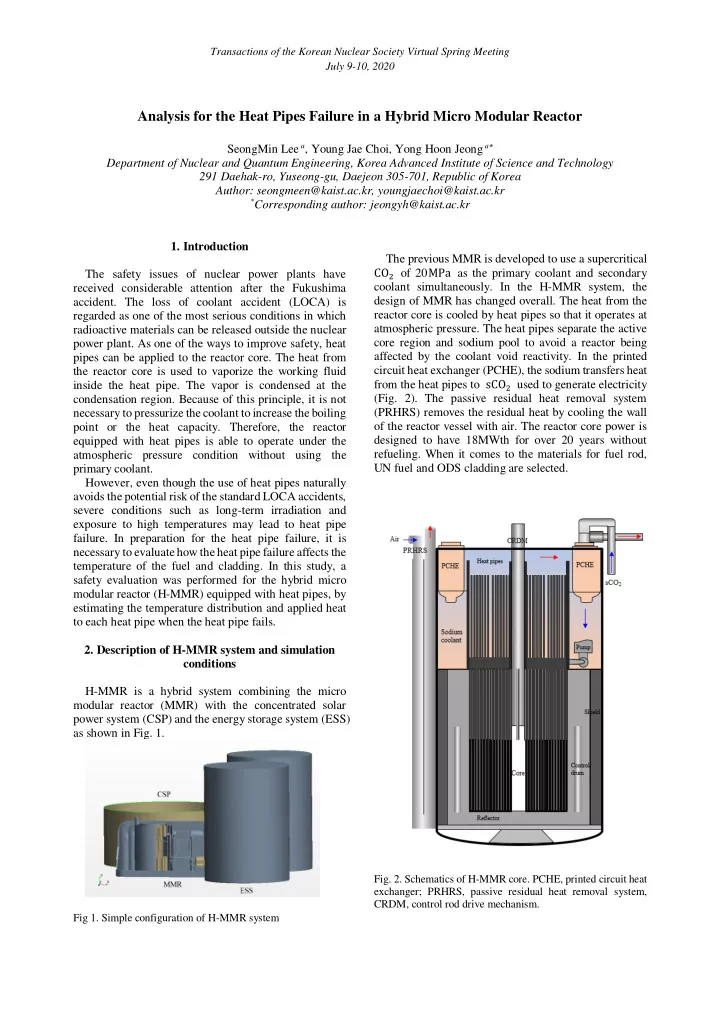
The previous MMR is developed to use a supercritical CO 2 of 20 MPa as the primary coolant and secondary The safety issues of nuclear power plants have coolant simultaneously. In the H-MMR system, the received considerable attention after the Fukushima design of MMR has changed overall. The heat from the accident. The loss of coolant accident (LOCA) is reactor core is cooled by heat pipes so that it operates at regarded as one of the most serious conditions in which atmospheric pressure. The heat pipes separate the active radioactive materials can be released outside the nuclear core region and sodium pool to avoid a reactor being power plant. As one of the ways to improve safety, heat affected by the coolant void reactivity. In the printed pipes can be applied to the reactor core. The heat from circuit heat exchanger (PCHE), the sodium transfers heat the reactor core is used to vaporize the working fluid from the heat pipes to sCO 2 used to generate electricity inside the heat pipe. The vapor is condensed at the (Fig. 2). The passive residual heat removal system condensation region. Because of this principle, it is not necessary to pressurize the coolant to increase the boiling (PRHRS) removes the residual heat by cooling the wall of the reactor vessel with air. The reactor core power is point or the heat capacity. Therefore, the reactor equipped with heat pipes is able to operate under the designed to have 18MWth for over 20 years without refueling. When it comes to the materials for fuel rod, atmospheric pressure condition without using the primary coolant. UN fuel and ODS cladding are selected. However, even though the use of heat pipes naturally avoids the potential risk of the standard LOCA accidents, severe conditions such as long-term irradiation and exposure to high temperatures may lead to heat pipe failure. In preparation for the heat pipe failure, it is necessary to evaluate how the heat pipe failure affects the temperature of the fuel and cladding. In this study, a safety evaluation was performed for the hybrid micro modular reactor (H-MMR) equipped with heat pipes, by estimating the temperature distribution and applied heat to each heat pipe when the heat pipe fails. 2. Description of H-MMR system and simulation conditions H-MMR is a hybrid system combining the micro modular reactor (MMR) with the concentrated solar power system (CSP) and the energy storage system (ESS) as shown in Fig. 1. Fig. 2. Schematics of H-MMR core. PCHE, printed circuit heat exchanger; PRHRS, passive residual heat removal system, CRDM, control rod drive mechanism. Fig 1. Simple configuration of H-MMR system

  2. Transactions of the Korean Nuclear Society Virtual Spring Meeting July 9-10, 2020 The operating temperature of heat pipe is determined 3. Results and discussion by sodium pool temperature distributed from 602 ℃ to 650 ℃ . Considering the temperature of fuel rod and Fig. 5 reveals the temperature distribution under operating limit of the heat pipe, it is preferable to use normal operating condition. The heat pipe number is indicated on the figure, e.g., number 1 means the central working fluid having a high operating limit under the low operating temperature. Therefore, potassium is selected heat pipe and number 7 means the corner heat pipe. With the assumption that the power distribution follows the for the working fluid because it has more marginal operating limits in the operating temperature of 660℃ cosine power shape, all safety analyzes were performed at a height of 0.6 m where maximum thermal power is (Fig. 3). The limitation of the heat pipe was calculated found. The maximum temperature is found at the edge of based on the five heat transport limitations [2]. outer cladding, surrounding the fuel and heat pipe. Due to the semi-circular heat pipe installed in the corner, the 100 K, D o =32 mm temperature is well distributed along the fuel assembly. 90 K, D o =28 mm K, D o =24 mm 80 K, D o =20 mm Power limitation (kW) Na, D o =32 mm 70 Na, D o =28 mm 60 Na, D o =24 mm Na, D o =20 mm 50 40 30 20 10 0 500 600 700 800 900 1000 1100 1200 1300 o C) Temperature ( Fig. 3. Operating limits as a function of operating temperature for potassium and sodium heat pipe with a diameter of D o and Fig. 5. Contour plot of temperature in the fuel assembly when annular wick structure. the core height is 0.6m. When the central heat pipe fails, the number 1 heat The heat pipe is applied to the reactor core, surrounded pipe could not remove heat from the center, more heat by fuel and cladding as indicated in Fig. 4. The active was applied to the adjacent heat pipe (Table. 1). For the core height is 1.2m and the gap conductance in each interface is assumed to be 5000 W/m 2 𝐿 as the gap heat pipe limitation, the failure did not cause damage to W/m 2 𝐿 the surrounding heat pipes since the amount of heat is conductance is about 5000 to 25000 still below the operating limit, which is approximately 33 depending on the height of the fuel [3]. kW. The temperature of cladding adjacent to the broken Each hexagonal fuel produces 20.4 kW of heat on heat pipe rose up to 1032℃ , which is similar to the average. The H-MMR has a sufficient safety margin in temperature of central fuel (Fig. 6). Although this terms of thermal power as the heat pipe is capable of temperature is below its melting temperature, the removing the heat up to approximately 33 kW. integrity of ODS cladding is not guaranteed above 800 ℃ [4]. Therefore, the reactor should shut down to replace the broken heat pipe with a new heat pipe. Fig. 4. Specific design parameters for the H-MMR core. This study has investigated the temperature Fig.6. Contour plot of temperature in the fuel assembly for the distribution and the applied heat to each heat pipe, using failure of number 1 heat pipe. commercial computational fluid dynamics code STAR- CCM+. In particular, safety for the reactor core was The effect of the failure for the corner heat pipe is evaluated when the heat pipe was damaged during shown in Fig. 7. The temperature around the broken heat operation. pipe is about 1000 ℃ , and this trend was quite similar to

  3. Transactions of the Korean Nuclear Society Virtual Spring Meeting July 9-10, 2020 the result when the central heat pipe broke. For the Acknowledgements adjacent heat pipe, applied heat increased up to 26.8 kW. This work was supported by the National Research Foundation of Korea (NRF) grant funded by the Korean government (Ministry of Science and ICT) (No. NRF- 2017M2B2B1071971). REFERENCES [1] H. Yu, D. Hartanto, J. Moon, and Y. Kim, A conceptual study of a supercritical CO2-cooled Micro Modular Reactor. Energies, Vol. 8, pp 13938-13952, 2015. [2] P. Nemec, A. Čaja, and M. Malcho, Mathematical model Fig.7. Contour plot of temperature in the fuel assembly for the for heat transfer limitations of heat pipe. Mathematical and failure of number 7 heat pipe Computer Modelling, Vol. 57, pp.126-136, 2013. [2] D. A. Reay, R. J. McGlen and P. A. Kew, Heat pipes: Heat Normal Number 1 Number 7 Theory, design and applications, Amsterdam : Butterworth- pipe operation failure failure Heinemann, 2016. Applied Applied Applied [3] M. Yamohammadi, M. Rahgoshay, and A. S. Shirani, Effect Number heat (kW) heat (kW) heat (kW) of central hole on fuel temperature distribution. Nuclear 0.0 1 20.6 20.6 Engineering and Technology, Vol. 49, No. 8, pp 1625-1635, 2017. 2 20.6 24.0 20.6 [4] S.J. Zinkle, J.L. Boutard, D.T. Hoelzer, A. Kimura, R. 3 20.6 20.6 20.7 Lindau, G.R. Odette, M. Rieth, L. Tan, and H. Tanigawa, 4 20.2 20.2 26.8 Development of next generation tempered and ODS reduced 5 20.6 20.7 20.6 activation ferritic/martensitic steels for fusion energy 6 20.4 20.4 23.7 applications. Nuclear Fusion, Vol. 57, No. 9, 2005. 7 10.1 10.1 0.0 8 20.2 20.2 26.8 Table I. Applied heat to each heat pipe depending on the assumed conditions. 4. Conclusion The H-MMR system using the heat pipes to transfer heat from the reactor core to PCHE was introduced. With given conditions described above, the temperature and heat applied to each heat pipe were obtained and the consequences of the heat pipe failure were analyzed with commercial computational fluid dynamics code. In normal operation conditions, the heat pipes kept the temperature in a satisfactory range. It was observed that the heat removal capacity of the heat pipe was sufficient for the current design. To make more efficient H-MMR, the diameter of heat pipe needs to be optimized, considering temperature, heat pipe limitations and reactor lifetime. Under the postulated accident, the damage to a heat pipe partially increased the fuel and cladding temperature. Since the operating temperature of cladding is lower than that of fuel, continuing to operate the reactor with the broken heat pipe cannot guarantee the integrity of the cladding because the temperature around the broken heat pipe exceeds 800 ℃. Meanwhile, there was no additional damage to the adjacent heat pipes right after the heat pipe failure because the heat applied to them is still below the limit. Therefore, it is expected that the reactor affords to shut down safely, using CRDM after the failure is detected.

Download Presentation
Download Policy: The content available on the website is offered to you 'AS IS' for your personal information and use only. It cannot be commercialized, licensed, or distributed on other websites without prior consent from the author. To download a presentation, simply click this link. If you encounter any difficulties during the download process, it's possible that the publisher has removed the file from their server.

Recommend


More recommend