
SLIDE 1
Aero Micro Midpoint Presentation
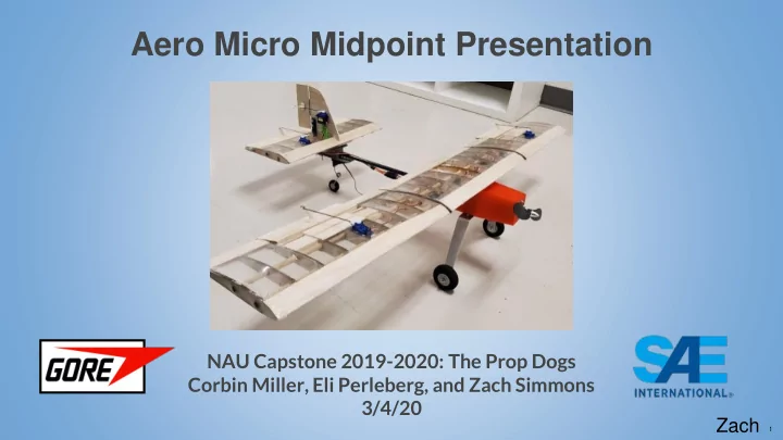
NAU Capstone 2019-2020: The Prop Dogs Corbin Miller, Eli Perleberg, and Zach Simmons 3/4/20 Zach
1
Aero Micro Midpoint Presentation NAU Capstone 2019-2020: The Prop - - PowerPoint PPT Presentation
Aero Micro Midpoint Presentation NAU Capstone 2019-2020: The Prop Dogs Corbin Miller, Eli Perleberg, and Zach Simmons 3/4/20 Zach 1 Agenda 1. Project Review and Description 2. Design Description and CAD model 3. Current State of System a.
1
SAE INTERNATIONAL 2
Zach
SAE INTERNATIONAL Paper # (if applicable) 3
Zach
SAE INTERNATIONAL
4
Zach
Figure 1: Current State CAD (Iso View)
Wing Control Surfaces Drive Fuselage Landing Gear
SAE INTERNATIONAL
5
Zach
Figure 2: Current State CAD (Side View) Figure 3: Current State CAD (Iso View)
SAE INTERNATIONAL
6
Subdesign Design Details Drive Propeller, motor, ESC, battery, wiring, and wire connectors Fuselage Frame geometry and material, drive housing, connections with carbon fiber rod, landing gear, and wing Wing Airfoil, chord length, wingspan, frame and cover material, wingspan connectors Landing Gear Geometry, material, steering mechanism In-Flight Control Linkages, motors, receiver, controller, control surface geometry
Table 1: Current State Model
Zach
SAE INTERNATIONAL
7
Corbin
Task Description Team Member Assigned Purchases Purchasing all materials and keep all invoices for later reimbursement All team members Wing ribs Laser cut balsa wood into Clark Y airfoil profile Zach: G code Corbin/Eli: Laser cutting Wing frame segments Connect ribs using ¼ inch wooden dowels Eli/Corbin Ailerons/Elevator Trim ends of wing sections and pin ailerons/elevator and glue servo and control horns in place connected with push pull rods Ailerons: All team members Elevator: Corbin
Table 2: Implementation Tasks Figure 4: Wing rib laser cutting Figure 5: Wing segments
SAE INTERNATIONAL
8
Task Description Team Member Assigned Fuselage Using solidworks 3D model fuselage to be able to fit drive components; motor, ESC, Battery, and receiver which are all held in place using velcro and motor mount Solidworks: Zach Mount wings to fuselage/empennage Using nuts and bolts connect base plate of center members of All team members Mount fuselage/empennage to carbon fiber rod Drill holes through shaft collar at rear of fuselage and front of empennage with carbon fiber rod in place and pin using nuts and bolts Eli/Zach Landing gear Bolt front landing gear with two bolts to bottom of fuselage and bolt rear steerable landing gear to empennage connector with servo embedded in empennage connector All team members Rudder Cut vertical stabilizer & rudder profile; attach both using a hinge, glue servo and control horn in place Eli/Corbin Controller Setup Solder ESC and motor and connect ESC to both battery and receiver. Set up controller to actuate servo motors Corbin/Zach Monokote Wrap the wing sections with monokote using sealing iron and heat gun to remove wrinkles All team members
Table 3: Implementation tasks
Corbin
SAE INTERNATIONAL
9
Eli
Wing Calculations
○ 3 wing segments of 13 inches ○ Desired length based on ERs and CRs
Figure 6: Airfoil Design
SAE INTERNATIONAL
10
Eli
Figure 7: First Laser cut design Figure 8: Final Wing Rib Design Figure 9: First Rudder Iteration Figure 10: Final Rudder Design
SAE INTERNATIONAL
11
Eli
Figure 11: Prototype of the Fuselage Figure 12: Final Result of Fuselage Figure 13: Prototype of Empennage Connection Figure 14: Final Design for Empennage Connection
SAE INTERNATIONAL
12
Eli
Figure 15: Final Result of Fuselage pre-Monokote Figure 16: Final Result
SAE INTERNATIONAL
13
Eli
SAE INTERNATIONAL
14
Corbin
Table 4: Engineering requirements
SAE INTERNATIONAL
15
Zach
Table 5: Bill of Materials and Budget
SAE INTERNATIONAL
16
Eli
Figure 17: Fuselage/Carbon Fiber Connection Figure 18: Preliminary Design
Bolt connection through shaft collar First design of carrying payload
SAE INTERNATIONAL
17
Eli
SAE INTERNATIONAL 18
SAE INTERNATIONAL
19
Drive Part Brand/Model Size Weight (oz) Cost ($) Prop APC Electric SF 8x4.7 8” dia x 4.7” pitch 0.25 2.45 Motor Scorpion HK-2520-1880KV 1” dia, 0.8” length (0.63 in^3) 3.64 80.00 ESC Scorpion Commander 15V 45A ESC SBEC (V3) 2.83”x1.18”x0.32” (1.06 in^3) 1.55 60.00 Battery Lumenier 1800mAh 3s 35c Lipo Battery 4.1”x1.34”x0.79” (4.34 in^3) 4.94 20.00 Total 6.03 in^3 10.38 162.45 Figure A1: APC Electric 8x4.7 SF Figure A2: Scorpion Motor Figure A3: Scorpion ESC Figure A4: Lumenier Battery Table A1: Drive Selection