
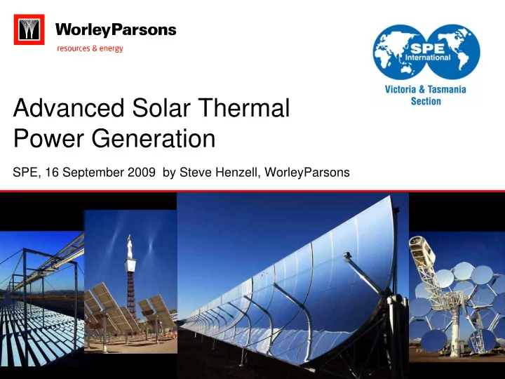
SLIDE 1
Advanced Solar Thermal Power Generation
SPE, 16 September 2009 by Steve Henzell, WorleyParsons
Advanced Solar Thermal Power Generation SPE, 16 September 2009 by - - PowerPoint PPT Presentation
Advanced Solar Thermal Power Generation SPE, 16 September 2009 by Steve Henzell, WorleyParsons Acknowledgements Steve Henzell Manager of Select, Conceptual Design at WorleyParsons Not an expert in Advanced Solar Thermal An
SPE, 16 September 2009 by Steve Henzell, WorleyParsons
2
Acknowledgements
Steve Henzell
Manager of Select, Conceptual Design at WorleyParsons Not an expert in Advanced Solar Thermal An expert in conceptual design and project assessment
Thanks to:
Barry Lake, who is an expert in Advanced Solar Thermal Geoff Wearne and Rod Touzel who are experts in electrical transmission
3
Agenda
Advanced Solar Thermal Power
Explained History of AST WorleyParsons involvement in AST Base load power plant Alignment with power demand
Other AST initiatives
Strengths and weaknesses of AST
Other renewable energy sources
Assessment of alternatives
Common challenges for renewable energy
What this means to the Oil & Gas industry
4
Concentrating Solar Power
G
Storage Solar Energy Concentrating parabolic dish Heat Transfer Medium Steam 3 Stage Condensing Steam Turbine Generator Molten Salt
5
15-Sep-09 5
How it Works
Solar Island
Parabolic mirrors concentrate sunlight onto collector tubes Mirrors track the sun from East to West Oil is heated in the collector tubes
Power Island
Heated oil from the Solar Island heats water in a boiler to produce steam The steam drives a conventional turbine to generate power
Storage
Operating hours of the plant can be extended by storing heat in molten salt for later recovery Conventional technology in nuclear power generation
5
7
Parabolic Troughs
8
Concentrating Solar Power Station
9
History of AST
10
Current Technology
Parabolic Trough
Proven technology SEGS plant Andasol 1 and majority of Spanish projects Maturity Scale: Highest
Central Receiver
BrightSource (direct steam) SolarReserve (molten salt) eSolar (mini direct steam) Maturity Scale: Medium
Compact Linear Fresnel Reflector (CLFR)
Ausra MAN Maturity Scale: Medium
11
CSP - Parabolic Dish (Stirling Engine)
12
Power Tower (Central Receiver)
13
Spain PS10 & PS20 Power Towers
Source: Koza1983
14
Solar Radiation
15
Australia’s Solar Radiation
16
Australia’s Power by 50km x 50km
17
Australia’s Solar Thermal Power Potential
18
The AST Technology
Proven technology
Successfully operated and improved for over 20 years in California
Ideally suited to areas of high solar intensity and little rain
Low environmental and social impact compared to other renewables
Provides utility-scale power from 50 to 300 MW
18
500
19
First Generation AST
For the initial AST project in Australia, the criteria is:
Proven performance / low technical risk Reliable revenue model Industry experience in design, manufacture, construction and
Parabolic trough concentrator like SEGS
For later generation AST projects may be a different technology:
Central Receiver Compact Linear Fresnel Reflector
2nd generation would have:
Lower cost Higher efficiency More storage
20
250 MW Plant Summary
Solar Field
Parabolic Troughs over 2 km x 3 km Solar Field Mirror Area: 1.5 million m2
Thermal Energy Storage
Two tank molten salt storage 1¼ hr storage at full plant output
Power Block
Export Power 250 MWe Conventional Steam Cycle
250 AFL football fields
21
Solar Engineering
System Performance Unit Value Net Turbine Output MWe 250.0 Parasitic Power % 12.3 Gross Turbine Output MWe 280.8 Steam Cycle Efficiency (Gross) % 37.8 Thermal Input to Steam Cycle MWt 742.8 Combined Solar Field Efficiency and Contingency % 51.1 Solar Input to Collector Field MWt 1,484
400.00 600.00 800.00 1,000.00 1,200.00 1,400.00 1,600.00 Net Turbine Output Gross Turbine Output Thermal Input to Steam Cycle Design Point Solar Block Ouput Thermal Output of Solar Field Collector Output Solar Input to Collector Field
22
A Melbourne CBD AST
23
50 100 150 200 250 1,250 1,500 1,750 2,000 2,250 2,500 Output (MW)
Load (MW) Hour
WA Average Daily Load & Output Profiles - Summer
Load (Nov-Feb) Output (J an)
23
AST Output and Network Load Coincidence
24
Typical Operating Day
June 15 6 12 18 24 500 1,000 1,500 2,000 Net_Electricity_Generated (MW)
Time Series
Q_dni Q_to_ts Q_from_ts Q_ts_Full Q_to_PB E_parasit Net_Electricity_Generated
Solar Radiation Energy from TES Solar Energy Dumped Net Elect Production Energy to Turbine Energy to TES
25
Steam Cycle Selected
Units AST Conventional Power Plant HP Turbine Inlet Pressure Temperature MPa °C 9.1 371 16.0 540 Reheat Temperature °C 372 540 Auxiliary Power MW 30.3 16.0
Parabolic trough 260 to 400°C
Heliostat with central receiver 500 to 800°C
Dish concentrator 500 to 1200°C
26
Solar Mirror Field Solar Steam Turbine
Heat Recovery Steam Generator
Exhaust Gas Natural Gas Fuel Solar Heated Oil Combined Cycle Steam Turbine
Combined-Cycle Plant Solar Plant
Solar Steam Turbine Gas Turbines
Solar System Boiler
High Pressure High Temperature Steam High Pressure Low Temperature Steam
Example of Separate Combined Cycle and CSP Plants
27
High Pressure High Temperature Steam Solar Mirror Field
Heat Recovery Steam Generator
Exhaust Gas Natural Gas Fuel Solar Heated Oil Combined Cycle Steam Turbine
Combined-Cycle Plant Solar Plant
Gas Turbines
Solar System Boiler
Saturated Steam
Integrated Solar Combined Cycle
Notice – only one steam turbine Eliminates need for additional interconnect and minimal additional water consumption
28
Why AST?
AST has
Peak load coincidence Output predictibility Daytime dispatchability and supplies into the peak price market Ability to store energy as heat rather than electricity Renewable Energy Certificate eligibility Steam based generation offering greater potential for integration with gas/coal based power generation (ISCC) Future proofing against fuel cost rises Competitive against diesel fuelled power generation
Challenges:
Still expensive but long term capital cost reduction potential Best supply locations are remote from infrastructure and markets
30
JVCEC Meeting
Wednesday 23rd September at Engineers Australia auditorium
Gordon Keen, ExxonMobil
By 2030, with projected economic and population growth, the world's total energy demand is expected to be approximately 35% higher than it was in 2005, despite significant gains in energy efficiency.
Each year, ExxonMobil develops The Outlook for Energy, a broad, in-depth look at the long-term global trends for energy demand and supply, and their impact on emissions.
This seminar will present key insights from The Outlook for Energy and will use these as a context to describe the Emissions Trading Scheme being developed in Australia.
31
Why Renewable Energy? CLIMATE CHANGE MRET
Mandatory Renewable Energy Target (20/20)
CPRS
Carbon Pollution Reduction Scheme REDP Renewable Energy Development Program
CEI
Clean Energy Initiative Solar Flagships
32
MRET 20/20
Original MRET 9,500 GWh by 2010
New MRET 20/20 45,000 GWh by 2020
Applies to electrical power generation only
Scheme favours lowest cost renewable energy technologies
Proven and mature Wind, hydro, biomass, solar hot water
Other government support for less mature technologies
Geothermal, solar thermal, solar PV, wave
Clean Energy Initiative
Carbon Capture and Storage Flagships Program Solar Flagships Program Renewables Energy Australia
33
CEI
Source: Australian Government, Department of Resources, Energy and Tourism
34
Proven Available now The cheapest renewable Variable Highly visible
35
Most common design used now is;
Three bladed
Up-wind
Horizontal axis
Pitch controlled
Steel, tubular tower
Epoxy/polyester blades
The Modern Wind Turbine
36
Wind Turbines Are Getting Bigger
Photos courtesy Verve Energy 30kW 30kW 225kW 225kW 225kW 225kW 600kW 600kW 600kW 600kW 1.8MW 1.8MW
37
Cathedral Rocks, SA, 2004
Roaring 40s Cathedral Rocks Wind Farm
38
Mature Technology
Over 20 years turbines have increased from 25 kW to beyond 2500 kW. Wind turbines have grown larger and
increased eight-fold
The cost of energy has reduced by a factor of more than five
The largest turbine currently in operation is the Enercon E126, with a rotor diameter of 126 metres and a power capacity of 6 MW
Offshore wind farms favour larger turbines and are pursuing designs of 5 MW and above
Land turbines have standardised on turbine size in the 1.5 to 3 MW range
Source: Global Wind Energy Council
39
Wind Power in Australia
50 wind farms, 1,306 GW
6 projects, 555 MW during 2009
Projects are getting bigger, more remote
Silverton, NSW 1000 MW+ Macarthur, VIC, 330 MW+ Hallett, SA, 130 MW Coopers Gap, QLD, 500 MW
40
Photovoltaics
Sunlight to Electricity
41
PhotoVoltaic (PV)
Flat Plate PV Thin Film PV Concentrating PV
42
Solar Systems Ltd. Dish/ PV
43
Solar Systems Experience
Solar PV cost per delivered unit of energy has fallen by over 60% in the last 5 years
Improvements in cell efficiency
35% when measured over the whole module Spin off from space program, providing high-reliability power to satellites
Improved mechanical design
Simplified PV receivers Improvements in construction methods
Source: Solar Systems Engineering Excellence Award
44
Dry Hot Rocks
45
Geothermal Resources Deep Temperatures Surface Heat Flow
Source: Geoscience Australia Geothermal Energy Project
46
Geothermal – “Hot Rocks”
47
Geodynamics 1MW Pilot Plant
Technical limits for materials and equipment
Failure of wellhead casing due to hydrogen embrittlement
Source: Geodynamics press releases
49
MRET 20/20
50
Wind Resources
51
Geothermal Resources
52
Solar Thermal Resources
53
Green Grid
Australia’s best wind resource Up to 5000 MW
Geothermal and Solar Thermal 1000 MW link
Link to NEM Further 3000 MW link
55
Gas for Power Generation
New renewable energy sources are base load plants
Can’t rely on new build coal fired power plants with large reserve capacity
Peaking sources
Hydro Gas
Hydro
Opportunities are rare Suffering from reduced rainfall
Gas
Numerous projects in each state Both base load and peaking power plants being installed
56
Gas for Power Generation
Competing government schemes
MRET and ETS have different cost mechanisms
Garnaut says that, perversely, this would increase coal-fired power stations as gas-fired power stations are crowded out
Are we ready for a market where gas is increasingly used for peaking service?
Rapid demand nomination changes Capacity to meet peaking service Rule changes