
SLIDE 1
)
- 5. Situated Agents (Robots)
Part 2: Planning and Motion. Multi Robot Systems
tems (SMA-UPC
Multi-Robot Systems.
Javier Vázquez-Salceda SMA-UPC
Multiagent Syst
https://kemlg.upc.edu
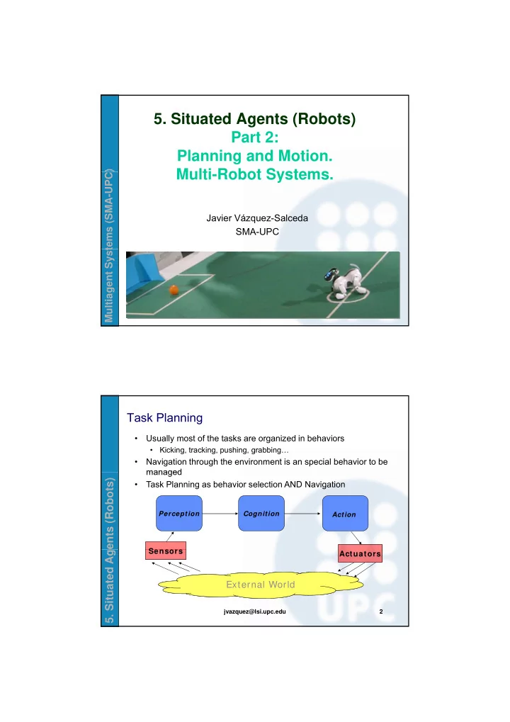
Task Planning
- Usually most of the tasks are organized in behaviors
- Kicking, tracking, pushing, grabbing…
- Navigation through the environment is an special behavior to be
managed
ents (Robots)
Action Perception
Sensors
Cognition
managed
- Task Planning as behavior selection AND Navigation
- 5. Situated Ag
jvazquez@lsi.upc.edu 2